Publication
Marwa AlAlawi, Regina Zheng, Abdullah Negm, Jiaji Li, Emma Li, Yasuaki Kakehi, Yoshihiro Kawahara, Junyi Zhu, Ticha Sethapakdi*, Stefanie Mueller*.
Bifur-circuits: Interactive and Modular Metamaterial Building Blocks Via Bifurcated Geometries
In Proceedings of UIST'26.
DOI PDF Video Slides Open Source
Video
Press
Coming Soon...
Slides
Coming Soon...
Bifur-circuits: Interactive and Modular Metamaterial Building Blocks Via Bifurcated Geometries
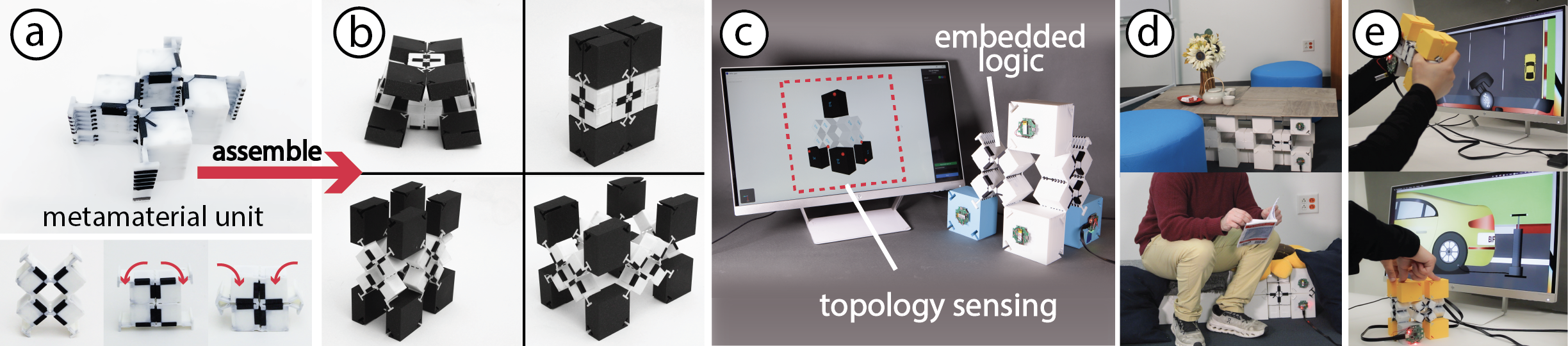
Mechanical metamaterials have gained traction in the HCI community for enabling interactive applications, including shape-changing displays and novel sensing paradigms. However, these structures typically support a limited set of stable geometric configurations, constraining the range of geometric expressions they can support through modularity. To overcome this constraint, we present Bifur-circuits, a mechanically and electrically modular, fully 3D metamaterial assembly toolkit. Bifur-circuits enables interactive geometries capable of exhibiting an exponentially increasing number of configurations as a function of units in an assembly. It accomplishes this through two layers of mechanical reconfiguration: at the assembly level, where modules can be added or removed, and at the configuration level via mechanical bifurcation, where structures split into new stable configurations upon reaching a critical geometric threshold. All units are internally routed such that electrical modularity produces a valid and unique circuit per configuration.
We contribute a Fusion 360-based construction tool, a Java-C++ simulation tool for real-time shape recognition, and a multi-material 3D printing fabrication pipeline. Our technical evaluation shows that Bifur-circuits maintain electrical connectivity after 10k cyclic compressions, and that shape recognition latency scales linearly with unit count (20 units maps to a 5-second detection time). Finally, we contribute two applications demonstrating Bifur-circuits' potential, across scales, for reconfigurable spatial environments and adaptive tangible user interfaces.
INTRODUCTION
Mechanical metamaterials are programmable structures of repeating units, leveraged to simplify complex mechanical designs or engineer custom material properties. Within the HCI community, these structures have been utilized for a variety of interactive applications such as capacitive sensors, reconfigurable antennas, and energy harvesters.
Conventionally, these fabricated metamaterial structures cannot be mechanically modified after fabrication; once built, they cannot be reprogrammed to a different shape or behavior without re-design and re-fabrication. To address this, researchers have explored building modular metamaterial systems to encourage their re-usability. While these prior works set a foundation for modular metamaterial structures, they are either limited to 2D or 2.5D construction, rely on multi-step manual fabrication processes, or are not electrically modular.
Electrical modularity refers to a system where discrete electrical units can be added, removed, or rearranged without rewiring or redesigning the overall system. Prior work leveraged this principle to simplify hardware prototyping and enable customizable consumer devices. However, in these systems, electrical modules are discrete functional components housed within or mounted onto a separate mechanical structure. Since the mechanical and electrical layers are independent, the geometric reconfiguration and electrical modularity have remained mutually exclusive.
Within HCI, existing modular and reconfigurable structures typically separate these domains; they either lack embedded electrical capabilities entirely, are constrained to planar configurations or 3D structures built from 1D lines, or require manual physical reassembly and rewiring to adapt to new geometries. Even in systems where these mechanical and electrical layers are not strictly mutually exclusive, they are generally limited to a single "flavor" of reconfiguration. Specifically, once a system is assembled, transitioning to a new shape requires complete physical disassembly of the modules, rather than supporting fluid, real-time deformation of the existing structure.
While mechanical modular systems allow users to construct different geometries at scale, that alone is insufficient for interactive applications. Without the ability to electrically sense the resulting topologies, the structure cannot respond to or communicate its configuration, which limits the range of applications. Thus, to prototype electro-mechanical interactions at scale, it is necessary to design systems that can integrate the strengths of both mechanical and electrical modularity.
We present Bifur-circuits, a system that combines electrical and geometric modularity to expand the design space and interactive expressivity of mechanical metamaterials. Bifur-circuits are reconfigurable metamaterial building blocks that can be linked together to systematically construct new interactive electro-mechanical structures. Bifur-circuits introduces two layers of mechanical reconfiguration: (1) at the assembly level, where discrete metamaterial modules can be added or removed, and (2) at the configuration level via mechanical bifurcation, where a structure can split into new stable configurations upon reaching a critical geometric threshold. Whereas conventional metamaterial units have a fixed number of states determined at fabrication, bifurcation unlocks an exponentially larger number of configurations as a function of the units in the assembly. Moreover, all units are internally routed such that, when linked, the electrical modularity produces a valid and unique circuit per configuration.
In summary, we make the following contributions:
- Bifur-circuits, a mechanically and electrically reconfigurable metamaterial geometry that acts as a building block for reconfigurable 3D metamaterial systems;
- a Fusion 360-based Bifur-circuits construction tool and Java-C++ simulation tool for shape recognition and interaction design;
- a fabrication pipeline via multi-material 3D printing for constructing mechanically and electrically modular Bifur-circuit structures;
- two technical evaluations on electrical endurance of Bifur-circuit units under mechanical deformation and shape recognition latency as a function of connected units in a single chain;
- two applications, including reconfigurable architecture and adaptive tangible user interfaces.
BIFUR-CIRCUITS WORKING PRINCIPLE
Bifur-circuits are auxetic metamaterial structures that are geometrically and electrically modular. Here, we cover the construction and sensing principles that govern their overall design and operation.
Bifur-circuits Construction Principle
Bifur-circuits are modular structures constructed from two building block geometries: (1) an auxetic kirigami metamaterial, which we refer to as metamaterial units, and (2) connectors that link these units together. There are two types of connector blocks: type AB (orthogonal) and type C (co-linear). Both metamaterial units and connectors are made of non-conductive material that is internally routed with conductive material.
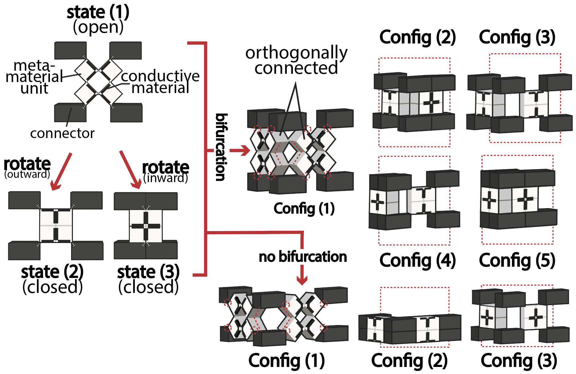
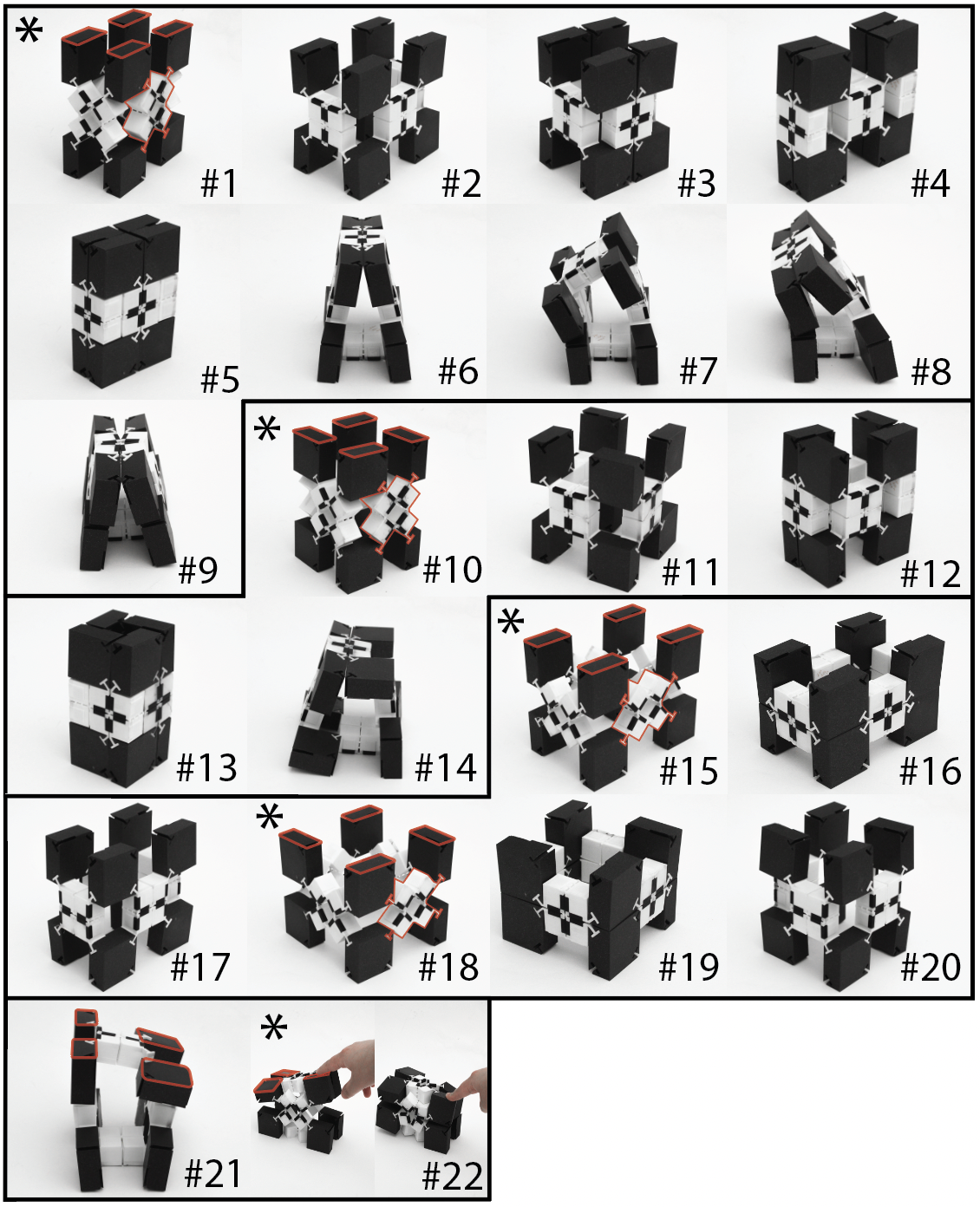
We form Bifur-circuit assemblies by press-fitting the units and connectors together. Bifur-circuit assemblies can be reconfigured into multiple geometric configurations. The reconfigurability of a single Bifur-circuit assembly grows exponentially as a function of metamaterial units in the system. This scalability is a result of two principles: (1) the intrinsic property of the auxetic kirigami metamaterial to assume three states (State(1)-open, State(2)-closed, State(3)-closed) due to rotation, and (2) bifurcating the assembly, by linking units adjacently or perpendicularly through connectors. Figure 2 illustrates how a single metamaterial unit yields only three states, while bifurcating it perpendicularly to another unit yields five configurations. Figure 3 shows how a 2×2×1 closed-loop assembly with a fixed block connector orientation has nine distinct configurations: five straight symmetric and four curved.
Bifur-circuits Sensing Principle
To identify which state a Bifur-circuit system is in on a unit level, we directly embed electrical interactivity into the structure. We do so by overlaying conductive material on the metamaterial inner edges that come into contact when a single unit assumes one of its three possible states. When these sides touch, a unique circuit is activated for each state, which helps us determine which state we are in on a unit level. As the entire assembly is electrically continuous, state detection at the unit level propagates to the assembly level, which allows the assembly to know its exact configuration.
Each block connector has four ports (nodes) with independent Data and Clock lines, that link to neighboring units. To map how units are connected, a designated "root" node scans its four ports, asks each neighbor to identify itself (node ID) and report its own connections (downstream I2C master). This process repeats recursively until the full assembly topology is discovered. The result is a global connection map published as structured data and a JSON file that is readable by our Bifur-circuit shape recognition software.
DESIGNING BIFUR-CIRCUITS
We identify the key parameters that govern the physical properties of Bifur-circuit assemblies and characterize their design space.
Design Parameters
In a Bifur-circuit assembly, the number of geometric states and the overall shapes produced upon reconfiguration depend on four design parameters (Figure 4).
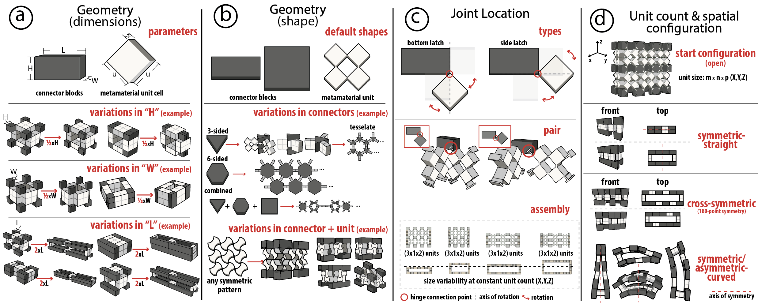
Geometry (dimensions and shape): Let H, L, and w denote the height, length, and width of the connector block, respectively, and let t and u represent the thickness and length of the metamaterial's unit square. By adjusting these ratios, we can produce various form factors and geometries for both blocks and metamaterials. For instance, halving the height can reshape a ring from a uniform cross-section to one with a central feature and thinner surrounding design. On the other hand, doubling a connector length creates a large hand-accessible hole, compared to a hole-free structure with the original ratio. These modular units can be further mixed and matched within these constraints. While we focus on rectangular and square metamaterial units and connector blocks, the same principle can be extended to any symmetrically patternable shape.
Joint Location: A metamaterial unit attaches to a connector at a vertex, known as the joint location. It can interlock with the block in two distinct orientations, termed bottom latch and side latch. In the bottom-latch configuration, the unit forms a 45° angle relative to the block's length, whereas in the side-latch configuration, the 45° angle is formed relative to the block's height. Rotating the connector block 90° about the y-axis — so that its height becomes its width — introduces two additional connection variations. At the assembly level, for a fixed m×n×p array initialized in the open state, varying hinge placement yields four distinct connection topologies, each with a unique height and footprint.
Unit Count: For a fixed unit count, the possible number of configurations and shapes that can be constructed by a Bifur-circuit assembly depend on the total number of units in the system and how they are connected to each other. These possible geometric shapes come in three flavors: symmetric-straight, cross symmetric (180 point symmetric), and curved-symmetric/asymmetric. Treating each connector as unique, despite visual redundancies, the total number of configurations follows:
$$ N(m, n, p) \propto 3^{m \times n \times p} $$
where m, n, and p are the units count along X, Y, and Z axes respectively. Since bending is permitted, all units are independent with 3 distinct states each, though some states may be less stable due to force distribution and tension/compression.Unit Stability: Stability describes whether the metamaterial retains its deformed shape after an external force is removed. Depending on the geometric and material parameters, Bifur-circuit modules can be monostable (a single equilibrium state) or bistable/tristable (two or three stable states). This stability profile is governed by the balance between the metamaterial's elastic springback force (determined by hinge geometry) and opposing forces, such as magnetic attraction. For example, a unit with sufficiently stiff hinges is monostable because the hinge springback force exceeds all other forces in the system, returning the module to its default State(1)-Open. By embedding magnets, the metamaterial can be transitioned to a tristable or bistable state. This force balance scales directly with the physical dimensions of the structure: for larger structures with longer, thinner hinges, the elastic springback force is sufficiently small due to beam bending mechanics that bistability is maintained geometrically without requiring magnets, while for smaller structures, embedded magnets provide the necessary supplementary holding force.
Design Space
By tuning the design parameters, Bifur-circuits enable a broad design space spanning form, compliance, and interaction.
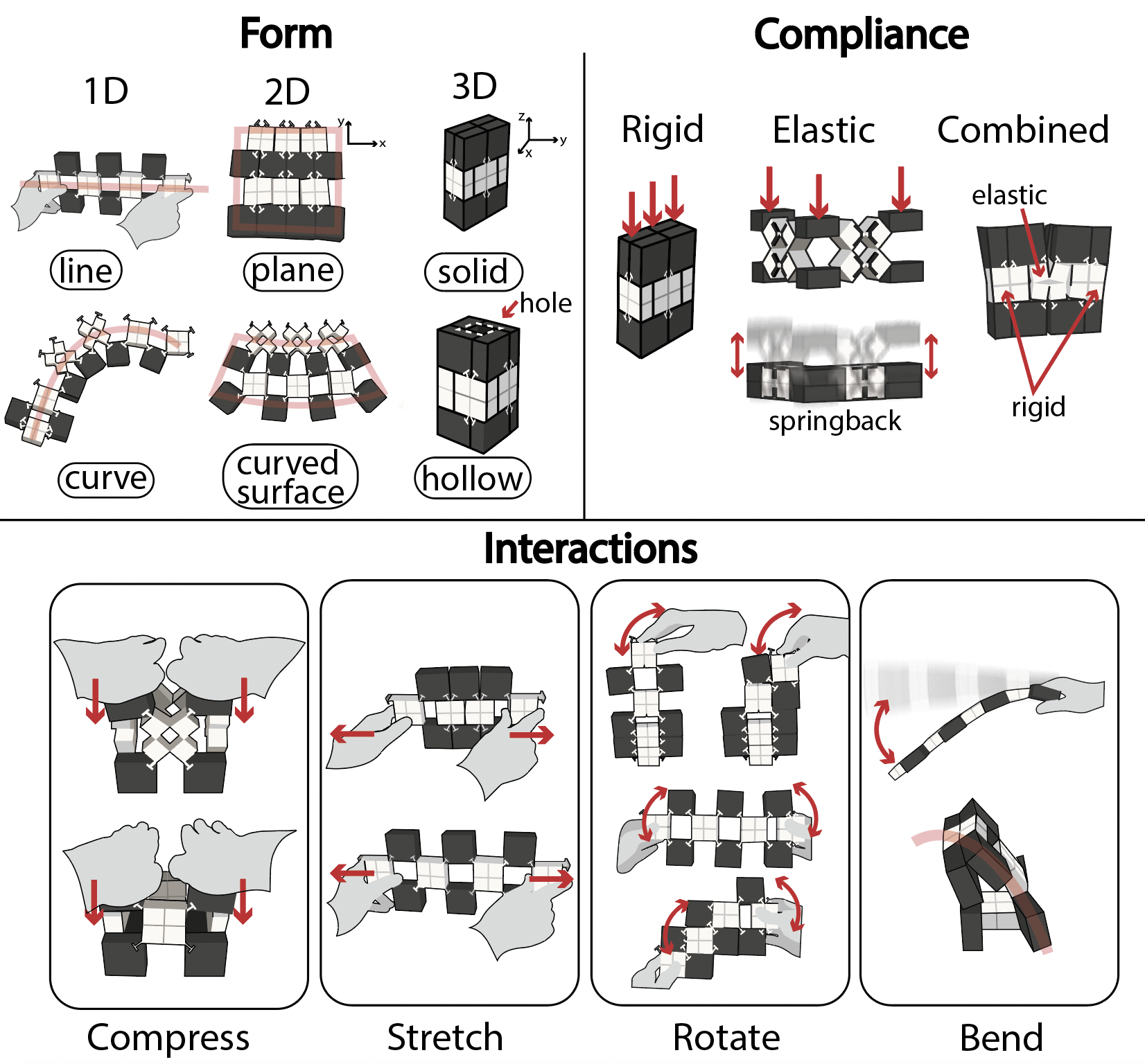
Form: Figure 5 illustrates how Bifur-circuit units can be linked along any XYZ combination to produce 1D, 2D, and 3D topologies. These topologies vary from straight or curved lines, planar surfaces, and hollow or solid volumetric geometries. Essentially, the resulting form is governed by the state of individual metamaterial units; selectively configuring these units propagates local geometric changes, such as curvature or hollowness, across the entire assembly.
Compliance: Compliance refers to the assembly's tendency to spring back or remain rigid upon removing an applied force. By tuning the stability of individual units through magnets, assemblies can be configured in one of three ways: fully rigid (maintaining a single state until reconfigured), fully elastic (returning to a default state after force removal), or spatially varying (mixing both rigid and elastic regions within the same structure).
Interaction: Bifur-circuit assemblies possess four inherent interaction affordances:
- Compression: When a normal compressive force is applied to an assembly, it transitions from one state to another.
- Stretching: Elongates unit chains, transitioning assemblies between compact and extended configurations.
- Rotation: Partial rotations are achievable via angular input about another fixed unit in the assembly or an external center of rotation.
- Bending: Occurs in two modes; geometrically, through selective unit configuration yielding curved yet stable forms; or structurally, when the length-to-cross-section ratio of an assembly exceeds ~3:1 and the assembly "deflects." Notably, some assemblies exhibit directional compliance — rigid in one orientation, yet flexible and deflecting when simply rotated by 90°, without altering unit states.
Modular Mechanical Structure & Design
For Bifur-circuits structures to be truly modular, they must meet the following design goals: support assembly and disassembly along all three axes (DG-1), have secure yet detachable joints (DG-2), enable on-axis hinges for unit-level reconfiguration (DG-3), exhibit intuitive connections (DG-4), and remain mechanically valid under in-plane rotation (DG-5).
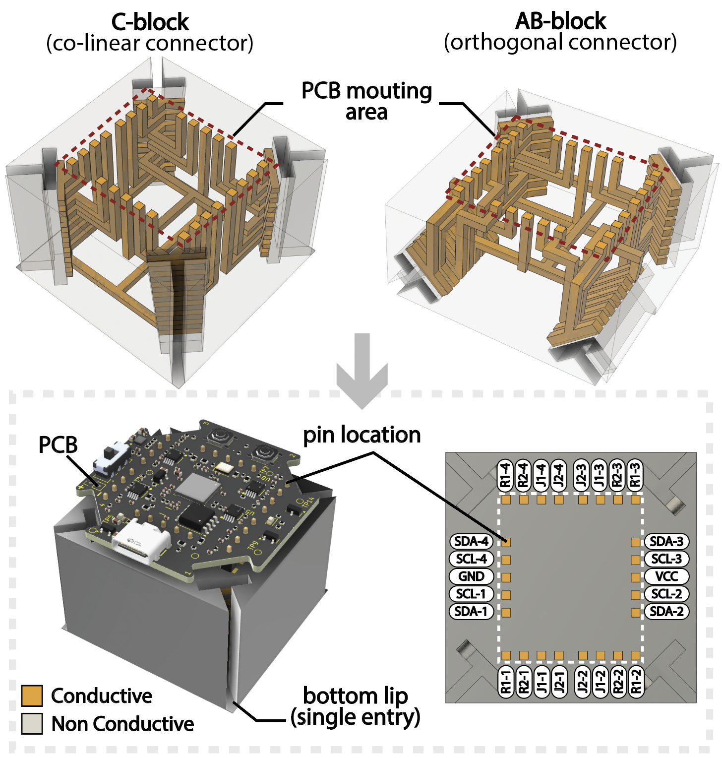
Type C & Type AB Connector Blocks (DG-1): To tessellate in XYZ, we introduce two connector block types: Type AB (orthogonal) for corners and depth, and Type C (co-linear) for linear 2D tessellation. Together, they link metamaterial units into a full 3D assembly.
Angled T-joint Connections (DG-2,3): Metamaterial units and connectors connect via a tight fit angled T-joint, whose geometry resists multi-directional forces and prevents disengagement. The angling co-locates the attachment entry point and joint axis exactly at the connector block's vertex. The T-joint is extruded on the Metamaterial Unit and recessed on the Connector block.
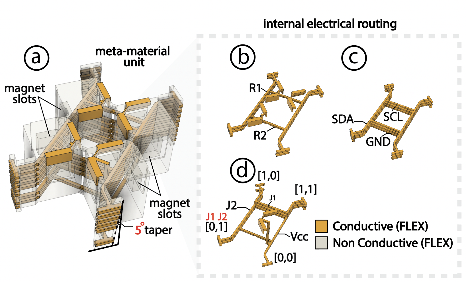
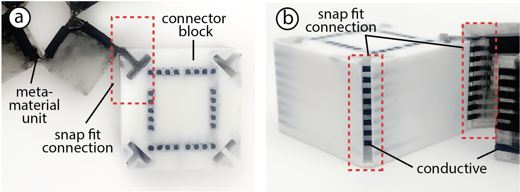
T-joint Taper on Metamaterial and Connectors (DG-2,4): We add a 5° taper on the T-joints to enforce a single-orientation insertion between units and blocks. This makes assembly less ambiguous, and ensures users do not inadvertently flip electrical connections by flipping the metamaterial unit.
Single Entry Way (DG-4): We incorporate a 0.2mm wall (2-layer thickness) to seal the narrow end of the T-joint taper at the back of the connectors, leaving only the wide end open at the front. This enforces a single insertion direction; flipping the block presents a solid face with no entry point, and the taper's asymmetry prevents forced reverse insertion.
Rotational Symmetry of T-joints (DG-5): To support flexible hinge placement while preserving the taper's directionality, the taper is rotationally symmetric across all four T-joint vertices of the metamaterial unit, and likewise on the connectors. In other words, each successive T-joint is rotated 90°, rather than mirrored.
Modular Electrical Structure & Design
For Bifur-circuits to be electrically modular, we define the following design goals: no electrical wires (or minimal wiring) (DG-1), connection at any orientation (DG-2), and maintained electrical validity after mechanical deformation (DG-3).
Internal Circuit Routing (DG-1,2): All connections are routed internally with conductive material, and non-conductive for structure and insulation. A Bifur-circuit connector's top face has 26 patch pin-outs: 2×4 logic pins R1, R2 (for determining the metamaterial unit state at each T-joint), 2×4 orientation pins J1, J2 (to determine which corner on the metamaterial is attached to the connector), and power/data lines VCC (x1), GND (x1), SDA (x4), SCL (x4) — enabling connector-to-connector data transfer through the metamaterial as a bridge. In summary, no wires are used, except for a surface-mount PCB on the top face.
Contact Points and Patches (DG-1,2,3): To establish an electrical connection between a metamaterial and connector upon mechanical joining, we make each T-joint carry 8 conductive patches that are rotationally symmetric across consecutive T-joints. These patches are ordered from top to bottom as: VCC, J2, J1, GND, SCL, SDA, R1, R2. We implement a tight-fit contact to ensure reliable electrical contact that persists under deformation. Notably, J1/J2 patch combinations differ across the four T-joints of the metamaterial unit (both, neither, J1-only, J2-only). This difference assigns each joint a unique local ID that encodes connection orientation.
Flexible Hinges and Additional Insulation (DG-3): Since electrical routing through the metamaterial unit traverses the hinges, which bend and deform during reconfiguration, the conductive material must remain intact under repeated deformation and must not short against neighboring units. To address this, we enforce the use of flexible conductive material for fabrication, and insulate unwanted contact points to prevent accidental shorting.
FABRICATING BIFUR-CIRCUITS
We describe the full end-to-end pipeline for Bifur-circuits, starting from editing designs in Fusion 360 to multi-material 3D printing with conductive and non-conductive filaments.
Making Designs
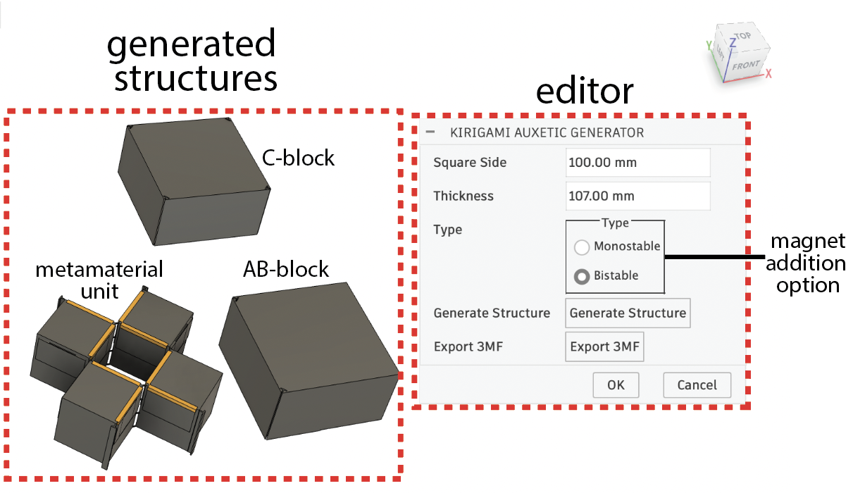
To help users design Bifur-circuit metamaterials and connectors for multimaterial 3D printing, we provide a custom Fusion 360 editor. The user begins by inputting the side length of the square unit and the thickness of the metamaterial unit (in mm). We set the minimum unit dimensions in the editor to 20mm and the minimum thickness to 28mm, which was calculated based on the number of connectors required, their thickness, and the separation distance between them. Next, the user can specify the stability of their unit. As bistable and tristable configurations require embedded magnets, the interface automatically generates pockets with a 1mm distance between the magnet location and the wall for those configurations. Finally, the user can preview what the final structure will look like and export it for fabrication.
Printing Metamaterial Units
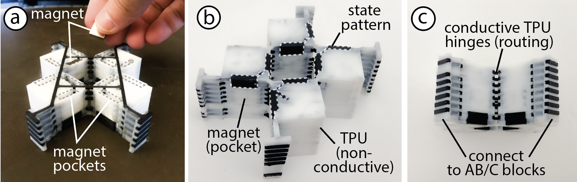
Bifur-circuit metamaterial units are fabricated via multimaterial FDM 3D printing using conductive (Filaflex 92A) and non-conductive (Sainsmart TPU 95A) filaments — 15% infill for non-conductive regions and 100% infill (99 perimeters) for conductive traces. Both materials are TPU-based to support flexible hinges and connection port routing. No supports or brims are used. Conductive elements are at least 1.5mm wide, with ≥1.5mm vertical separation between patches. For bistable/tristable configurations, printing is paused to insert N45 Neodymium magnets (3/8×3/8×1/8", CMS Magnetics), with 1mm separation per engaged pair and opposing polarities on facing surfaces.
Printing Connectors
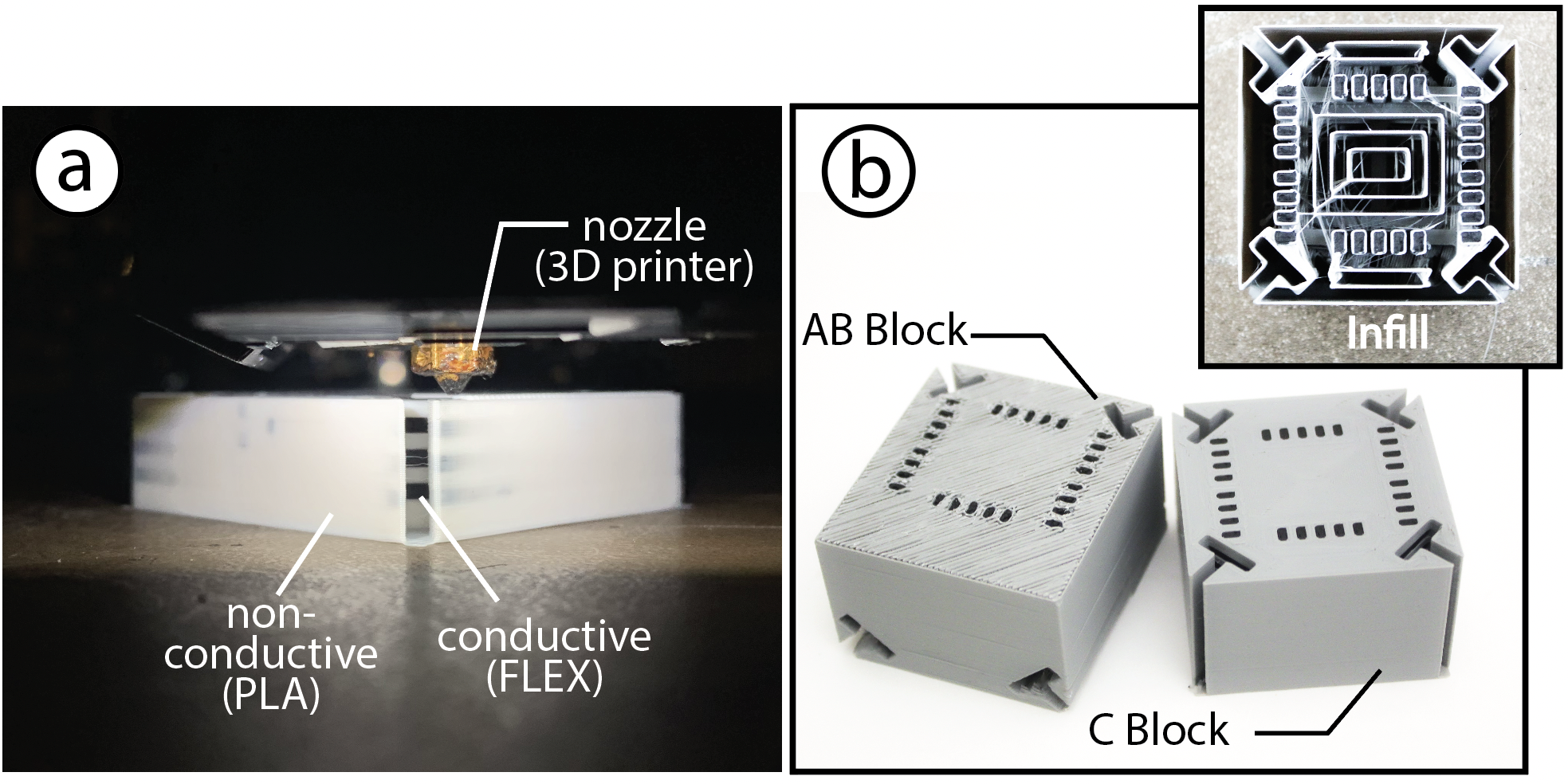
Connectors are printed in solid PLA (15% infill, 1-line perimeter, concentric pattern) as rigid components, while the conductive traces are printed with Filaflex at 100% infill with 99 wall perimeters and a rectilinear pattern. We did not use any supports or brims, except for the AB connector block, where our editor automatically generates support elements for the T-joint cavities printed at an angle. Each conductive element is at least 1.5mm in dimension, with 1.5mm non-conductive separation between conductive traces in the Z direction.
Assembly and Interaction Programming
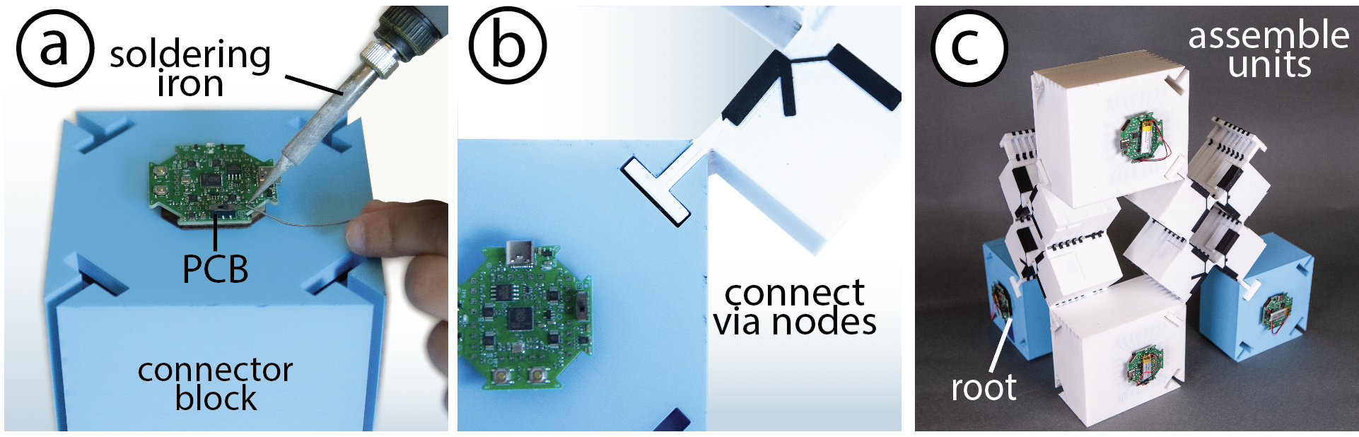
We assemble by connecting the metamaterial units to the connectors and form shapes. Bifur-circuits do not need wires for connections aside from the "root block/node." Our PCBs are mounted directly into each connector block's conductive patches through heat pressing.
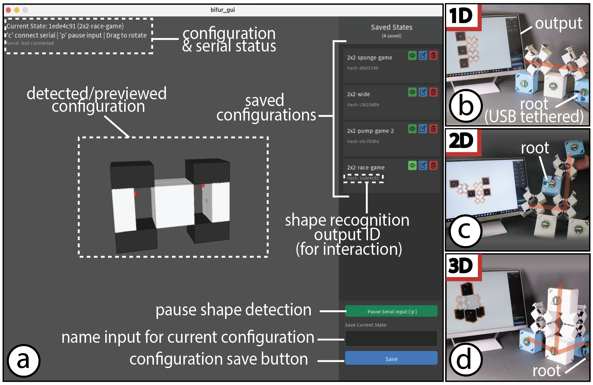
To help users program Bifur-circuit interactions, we developed an interactive UI in Java and Processing that lets users preview their physical assembly as a 3D model, save named geometry configurations, and export corresponding C++ code of the geometry to a reusable C++ library. A template sketch allows users to recall these saved states and map them to custom interactions. Our tool supports 1D, 2D, and 3D Bifur-circuit assemblies.
TECHNICAL EVALUATION
We performed a technical evaluation to determine the maximum number of units that can be integrated into a single branch of a Bifur-circuit node. We also assessed the electrical durability of our conductive 3D-printed hinges under reverse cyclic loading and cyclic compression in two orientations.
Latency as a Function of Units
In this evaluation, we assess topology-discovery latency as a function of chain length, accounting for material resistance and I2C protocol constraints.
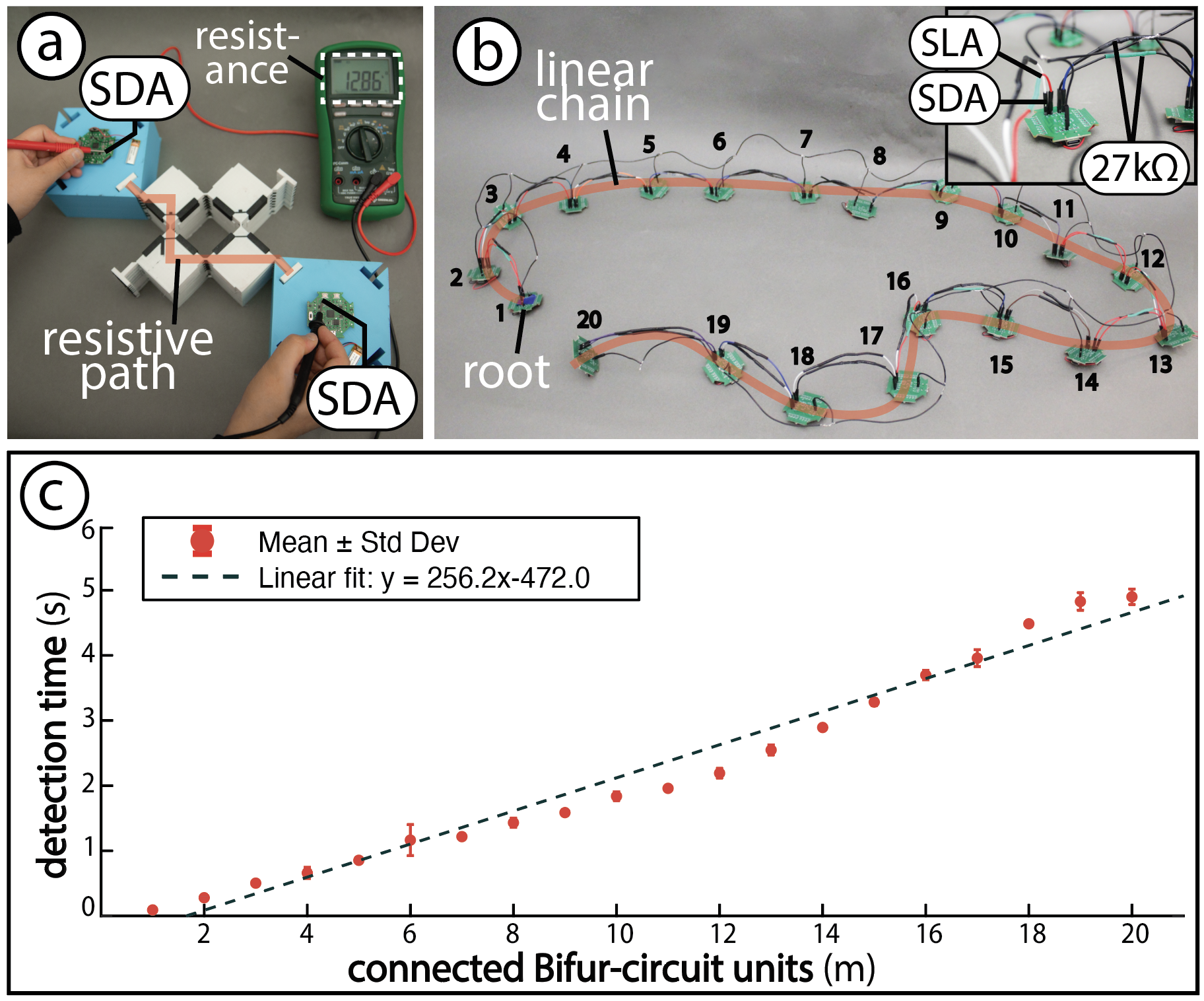
Setup: We chained 20 Bifur-circuit PCBs with 27kΩ resistors between neighboring I2C lines, all sharing a common ground.
Procedure: To implement the correct resistance in our evaluation, we physically measured SDA and SCL port resistances across the largest possible path for both the largest and smallest 3D-printable element sizes (10 samples each; Table 1). We then chained 20 PCBs with 27kΩ inter-node resistances, double the measured values for conservative testing, and recorded topology-discovery latency as a function of chain depth over three runs at 20 kHz.
| Measured Ports | Largest Unit | Smallest Unit |
|---|---|---|
| SDA (Ω) | 13.08 ± 0.80 kΩ | 15.215 ± 0.2549 kΩ |
| SCL (Ω) | 12.09 ± 1.91 kΩ | 17.001 ± 0.2309 kΩ |
Table 1: Measured I2C line resistances across 10 samples for the smallest and largest Bifur-circuit unit/connector sizes.
Results: Figure 14 shows a linear increase in detection time (t) with the number of connections (m), following:
$$ t_{detection} = 256.2 \times m - 472 $$
with a regression R² = 0.9727, which is consistent with the O(n) time complexity of the I2C neighbor discovery algorithm. Minor deviations are attributed to low battery power or the inter-signal dead time (pause) built into the I2C protocol.Electrical Connectivity Endurance
Setup: Our apparatus consists of a texture analyzer programmed to apply 10k compressive cycles to metamaterial unit samples, with pauses every 1k to measure connectivity (resistance) through a multimeter (Model: Greenlee DM-820A). We fabricated four samples with 100% infill and 3:2 (width to length) hinge geometries, all with rectangular cross sections and a fixed hinge width of 1.5mm. A custom 3D-printed jig with extruded pegs, mounted on the analyzer, enables compression in two orientations. We refer to continuous deformation in orientation (1) as cyclic loading-1 and in orientation (2) as cyclic loading-2; we define alternating between orientations each cycle as reverse cyclic loading.
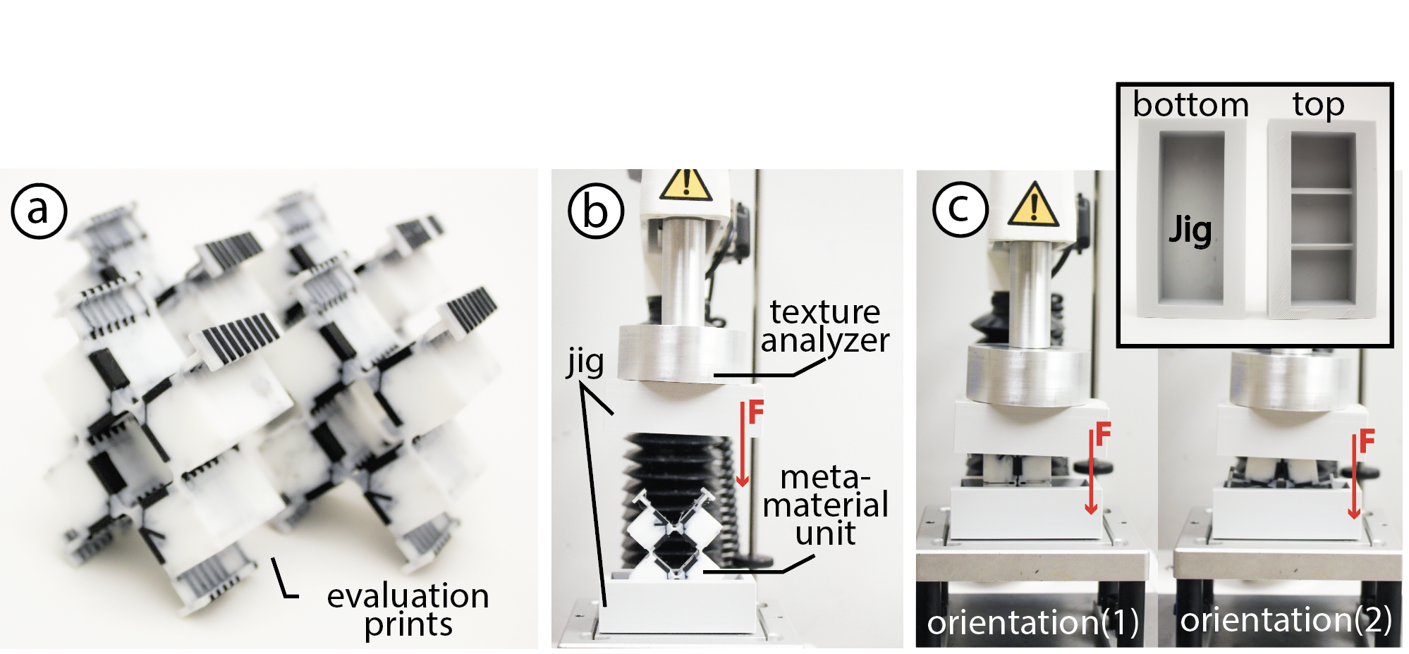
Procedure: We conducted four evaluations on the metamaterial samples. Samples 1–3 were subjected to 10k cycles using a texture analyzer: cyclic compression in orientation (1), cyclic compression in orientation (2), and alternating between orientation 1 and orientation 2 in successive 1k-cycle intervals, respectively. The analyzer was configured with a pre-test speed of 1 mm/s, test speed of 20 mm/s, post-test speed of 2 mm/s, a target displacement of 20 mm, and an auto force trigger of 1 N. For Sample 4, we performed manual reverse cyclic compression up to 10k cycles to reflect typical human interaction with the metamaterial units. Across all tests, electrical connectivity was measured every 1k cycles using a multimeter across the four metamaterial joints, and hinges were visually inspected for damage.
Results: Through our experiments, we found that the structures withstand 10k rotations under both reverse and same-orientation cyclic loading both mechanically and electrically. While higher cycle counts are possible, 10k is considered sufficient based on material fatigue literature.
APPLICATIONS
Bifur-circuits provide a toolkit for building reconfigurable structures at various scales. In this section, we demonstrate two application domains: shape-changing spatial environments and interactive tangible interfaces.
Programmable Spatial Environments
Modern architecture increasingly explores furniture that morphs between states — enabling spaces to adapt, re-purpose, and respond dynamically to physical change. Bifur-circuits' modular, scalable, and interactive construction makes it particularly well-suited for programming such human-scale reconfigurable environments.
In this application, we demonstrate a human-scale Bifur-circuit assembly as a reconfigurable piece of furniture that dynamically shifts in scale and shape while interactively updating a digital door sign to reflect the occupant's current activity. Comprising 24 metamaterial units and 24 blocks, the assembly measures 40cm × 30cm × 110cm when fully expanded and supports a highly versatile range of physical states. Below, we highlight three distinct forms.
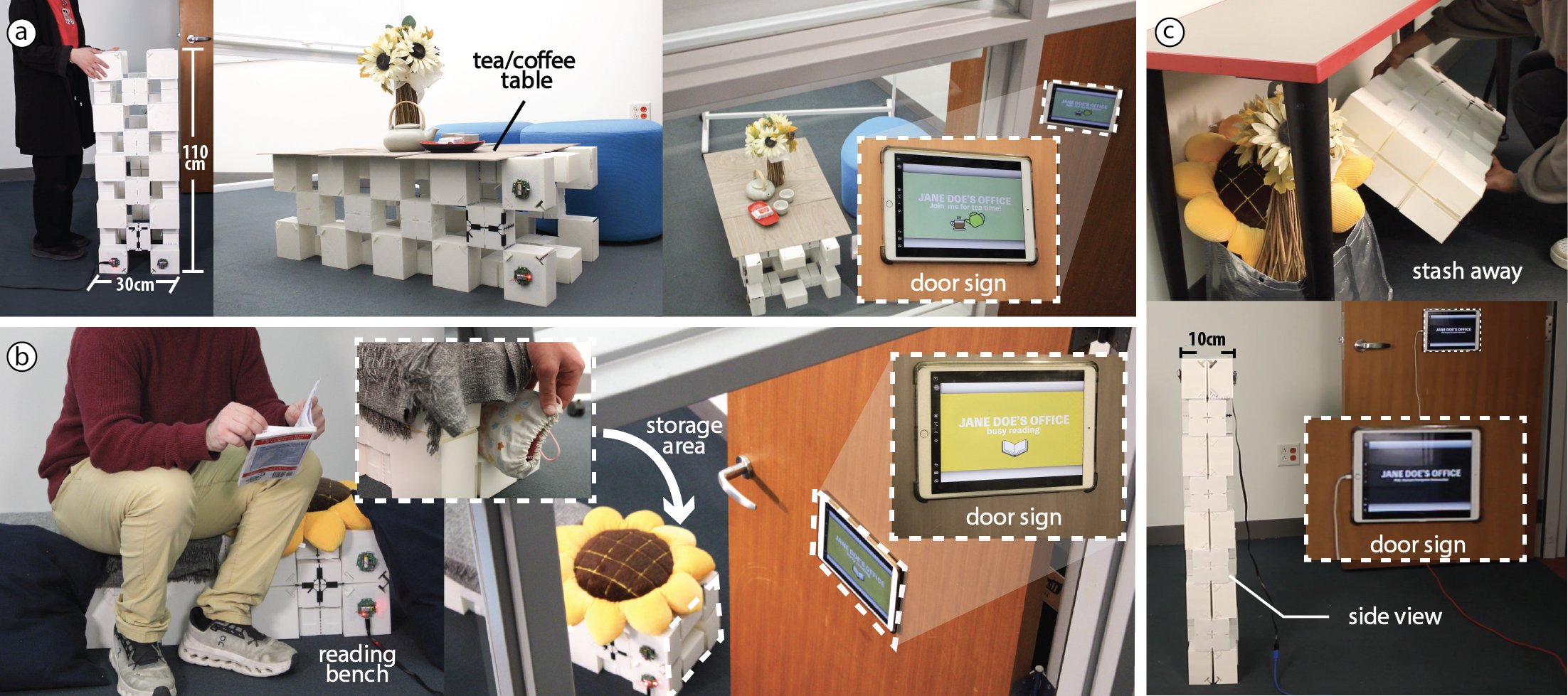
Tea Table (Fully Expanded): When fully expanded, the structure transforms into a large, open table suited for hosting. In this configuration, the sign shifts its message to invite others in.
Chair & Storage (Fully Retracted-Hole): In its fully retracted state, the assembly becomes a compact chair with an integrated storage compartment beneath the seat. The storage space accommodates books or other personal belongings. Sensing that the user has settled in to read, Bifur-circuit signals the environment to respond with the digital door sign displaying: "Busy reading."
Flat Surface (Fully Collapsed-No Hole): In the third showcased configuration, the assembly is set to a fully collapsed planar configuration, with no holes, by removing the corner (AB) connector blocks then rotating them parallel to the co-linear (C) blocks. The resulting structure is easy to stow on a shelf or under a table, indicating the end of use.
Reconfigurable Tangible User Interfaces
Drawing on Bifur-circuits' multiple stable states, we demonstrate a tangible controller that reconfigures into distinct form factors without swapping hardware. Unlike commercial accessories, such as game console peripherals that require separate attachments to mimic steering wheels or tennis rackets, a single Bifur-circuit assembly shifts between functional shapes on its own. We use only a single root connector for ergonomic reasons, which also suffices computationally as all programmed states are symmetric, and sensing only two metamaterial units is enough to determine the full assembly shape.
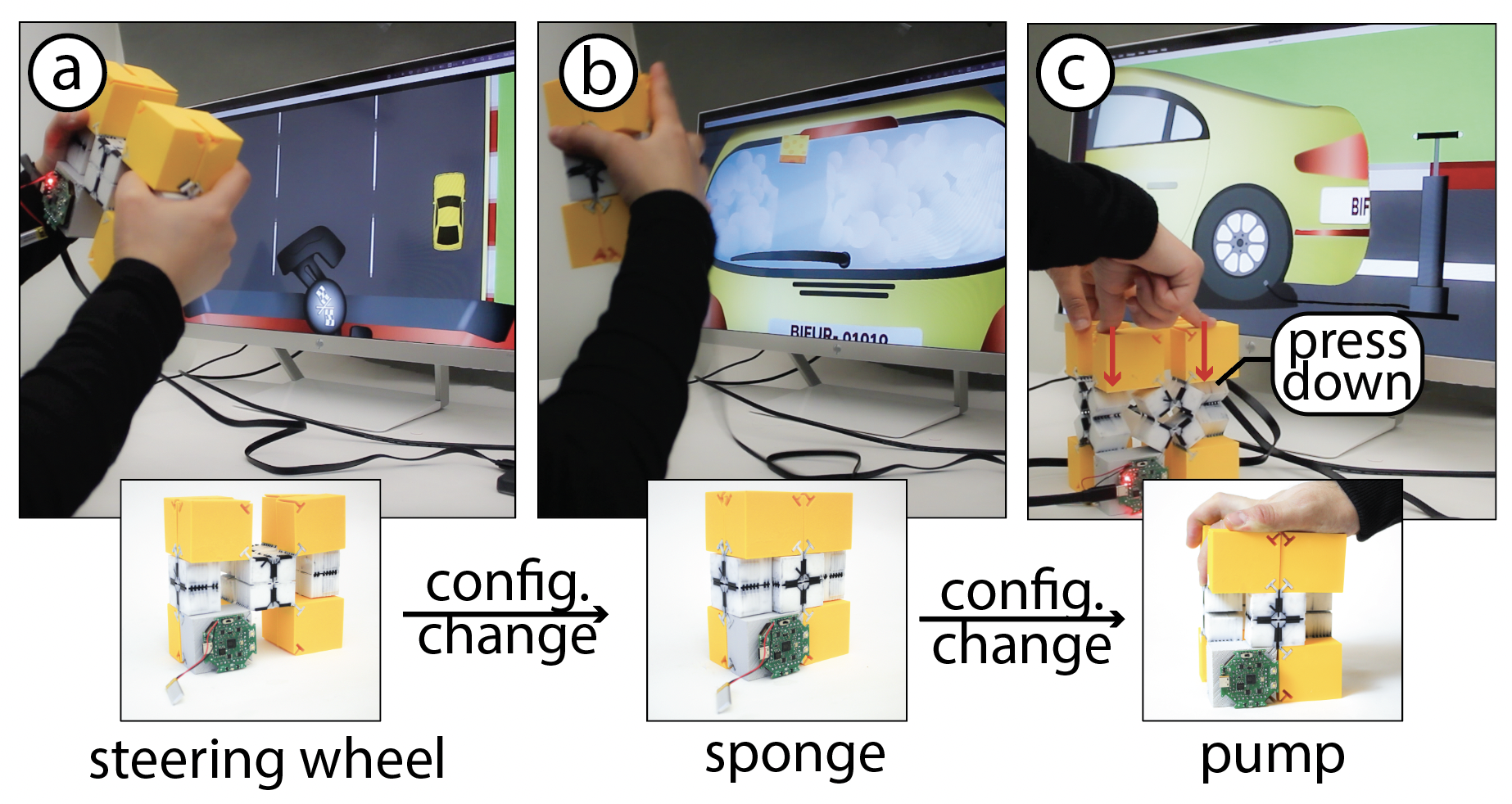
In our prototype, state 1 forms a steering-wheel grip triggering a racing game (a); state 2 collapses into a sponge-like block to wash the car's window (b); and compressing the assembly like a pump between states 3 and 4 inflates the car's tire (c). Because units can be added or removed like building blocks, users can further customize both the controller's form factor and its mapped interactions.
DISCUSSION AND FUTURE WORK
In this section, we outline the limitations and future directions of Bifur-circuits.
Shape Memory of the Structure: TPU's visco-elastic property introduces a directional shape memory, which lets Bifur-circuit structures, which have multiple configurations, retain a reconfiguration bias toward the most recently held/compressed configuration. Users can reprogram this biased state to any Bifur-circuit state by simply holding the assembly in that desired configuration then letting go. Our preliminary evaluations show that this bias is sustained for over 12 hours across our smallest fabricatable connectors and units. In future work, we would like to use this property as a tunable feature.
Power Consumption as a Function of Units: The conductive material's high resistivity (3.9Ω·cm) results in significant resistance across Vcc (15–25kΩ) and GND (13.5k–25kΩ) lines between the largest and smallest fabricatable connector-metamaterial pairs. This resistance prevents reliable power delivery to other connectors through the traces despite functional I2C communication. To work around this material constraint, we use a rechargeable Lithium Polymer cell battery (GM301030-PCB 62mAH) on every PCB, which can be charged directly with ~45 minutes runtime under continuous sensing. We can extend battery life via interrupt-driven sleep/wake cycles or by turning blocks off when sensing is inactive. Future work using flexible perfect conductors would eliminate this constraint and enable a single block to power the entire assembly.
Sensing Stability: Sensing stability relies on binary detection of connected/unconnected Vcc lines, making it robust to environmental noise. However, stability is affected by how well physical contact between blocks and units are maintained. The visualizer can serve as a diagnostic tool; if the rendered output looks different from the physical structure, then the user deduces the presence of a faulty connection.
Latency: As shown in the technical evaluation, detection time scales linearly with both the algorithm's complexity and the increased resistance introduced by the 3D-printed material. However, full detection is not always necessary: when a structure only needs to morph between a known subset of states, far fewer microcontrollers are required (e.g., 1 for 3 shapes, 2 for 4), since not all neighboring blocks need to be active to distinguish the desired states. In future work, we plan to replace redundant microcontrollers with passive "buffer blocks," paired with a sensing-placement tool that identifies the shortest sensing path needed to detect all target states — reducing detection time by avoiding unnecessary sensing.
Simulation Support for Bending & Deformation Prediction: Our shape recognition software graphically simulates Bifur-circuit assemblies. While bent configurations are not yet visually simulated, they are recognized as independent states and are supported for interaction design. In addition, our Fusion interface does not currently support deformation prediction while our Java interface only renders user-created deformation states. We would like to implement these features in future iterations.
Communication over WiFi: Our PCBs use an RP2040 microcontroller, which can transmit data over WiFi. In future work, we plan to have Bifur-circuit operate fully untethered, transmitting topology and interaction data over WiFi without any USB connection.
Extending Bifur-circuits to Heterogeneous Connector and Metamaterial Unit Geometries: In future work, we would like to explore mixing connector and metamaterial unit geometries (e.g., triangular, hexagonal, rectangular, curved) of different sizes within a single assembly, which are compatible with our current circuitry and routing, enabling regional variation and smooth interpolation between different structural scales.
Extending Bifur-circuit Interaction Space: Our current system focuses on state recognition of any user-assembled modular structure, but it is readily extensible to other interaction paradigms. For example, capacitive touch sensing could be integrated onto connector blocks or metamaterial units with additional routing and minor PCB modifications. SMD accelerometers or IMUs can be added to the existing PCB without altering block geometry or routing.
CONCLUSION
In this paper, we presented Bifur-circuits, a mechanically and electrically modular interactive metamaterial system supporting reconfiguration through two levels: unit insertion and removal, and mechanical bifurcation. By integrating structure and electronics into a single unified system, our approach enables metamaterial assemblies that maintain electrical continuity after more than 10k rotations, with linearly-scaled latency as a function of added units. Through a range of applications, from responsive furniture to adaptive tangible user interfaces, we demonstrated how Bifur-circuits scale across objects and environments. Supporting these applications, our Fusion 360 design tool enables custom structure generation, while our shape recognition interface detects, saves, and maps configurations to interaction design workflows. More broadly, our work demonstrates the potential of metamaterials as modular, interactive building blocks that move well beyond the three default states of traditional auxetic metamaterials. With Bifur-circuits supporting 1D, 2D, and 3D construction alongside a rich set of interaction affordances (compression, elongation, bending, and rotation), we envision a future where metamaterials are deeply integrated into everyday interactive applications.
ACKNOWLEDGMENTS
We would first like to thank Ahmad Taka and Travis Ziegler for their unwavering support and help in building the algorithm and PCB for Bifur-circuits. We would also like to thank Mark Feldman and Rei Sakura for their general advice during early prototyping, Jack Forman for his help with 3D printing, and Dr. Barbara Hughey and Nicholas Ignacio for giving us access to a texture analyzer. Finally, we would like to thank Ezekiel Daye for his help with early prototyping work. This project was kindly supported by ASPIRE Funding from Japan's Science and Technology Agency, and the Bahrain Crown Prince International Scholarship Program.
REFERENCES
- Stephan Hankammer, Ruth Jiang, Robin Kleer, and Martin Schymanietz. 2016. From phonebloks to google project ara. a case study of the application of sustainable mass customization. Procedia Cirp. Elsevier.
- H MA Kolken, and AA Zadpoor. 2017. Auxetic mechanical metamaterials. RSC advances. Royal Society of Chemistry.
- Yunfang Yang, Perla Maiolino, Yan Chen, and Zhong You. 2021. Three-dimensional kinematic metamaterial with tuneable directional permeability. arXiv preprint arXiv:2102.08821.
- Ken Nakagaki, Artem Dementyev, Sean Follmer, Joseph A. Paradiso, and Hiroshi Ishii. 2016. ChainFORM: A Linear Integrated Modular Hardware System for Shape Changing Interfaces. In Proceedings of the 29th Annual Symposium on User Interface Software and Technology. https://doi.org/10.1145/2984511.2984587
- Jesse T Gonzalez, Sonia Prashant, Sapna Tayal, Juhi Kedia, Alexandra Ion, and Scott E Hudson. 2023. Constraint-Driven Robotic Surfaces, At Human-Scale. In Proceedings of the 36th Annual ACM Symposium on User Interface Software and Technology. https://doi.org/10.1145/3586183.3606740
- Ahad M Rauf, Jack S Bernardo, and Sean Follmer. 2022. Electroadhesive auxetics as programmable layer jamming skins for formable crust shape displays. arXiv preprint arXiv:2211.05375.
- IGN. 2011. Switch 2 Sports Accessories Bundle.
- Yanbin Li, Caizhi Zhou, and Jie Yin. 2024. Geometric mechanics of kiri-origami-based bifurcated mechanical metamaterials. Philosophical Transactions of the Royal Society A: Mathematical, Physical and Engineering Sciences. https://doi.org/10.1098/rsta.2024.0010
- Martin Nisser, Leon Cheng, Yashaswini Makaram, Ryo Suzuki, and Stefanie Mueller. 2022. ElectroVoxel: Electromagnetically actuated pivoting for scalable modular self-reconfigurable robots. In 2022 International Conference on Robotics and Automation (ICRA).
- Linzhi Li, Hongyi Yao, and Shengli Mi. 2023. Magnetically driven modular mechanical metamaterials with high programmability, reconfigurability, and multiple applications. ACS Applied Materials & Interfaces. ACS Publications.
- Ken Nakagaki, Sean Follmer, and Hiroshi Ishii. 2015. LineFORM: Actuated Curve Interfaces for Display, Interaction, and Constraint. In Proceedings of the 28th Annual ACM Symposium on User Interface Software & Technology. https://doi.org/10.1145/2807442.2807452
- Ayah Bdeir. 2009. Electronics as material: littleBits. In Proceedings of the 3rd International Conference on Tangible and Embedded Interaction. https://doi.org/10.1145/1517664.1517743
- Kaili Xi, Jingsong Wei, Xiao Zhang, Jiayao Ma, Zhong You, Changqing Chen, and Yan Chen. 2025. A kinematically Bifurcated Metamaterial for Integrated Logic Operation and Computing. Advanced Science. https://advanced.onlinelibrary.wiley.com/doi/abs/10.1002/advs.202509829
- Andrew Horwood, and Nachiappan Chockalingam. 2023. Chapter 2 - Principles of materials science. Clinical Biomechanics in Human Locomotion. Academic Press. https://www.sciencedirect.com/science/article/pii/B978032385212800002X
- Marwa AlAlawi, Regina Zheng, Sooyeon Ahn, Katherine Yan, Ticha Sethapakdi, Junyi Zhu, and Stefanie Mueller. 2025. Meta-antenna: Mechanically Frequency Reconfigurable Metamaterial Antennas. In Proceedings of the 38th Annual ACM Symposium on User Interface Software and Technology. https://doi.org/10.1145/3746059.3747760
- Alexandra Ion, Ludwig Wall, Robert Kovacs, and Patrick Baudisch. 2017. Digital Mechanical Metamaterials. In Proceedings of the 2017 CHI Conference on Human Factors in Computing Systems. https://doi.org/10.1145/3025453.3025624
- Jun Gong, Olivia Seow, Cedric Honnet, Jack Forman, and Stefanie Mueller. 2021. MetaSense: Integrating Sensing Capabilities into Mechanical Metamaterial. In The 34th Annual ACM Symposium on User Interface Software and Technology. https://doi.org/10.1145/3472749.3474806
- Jake Robert Read, Leo Mcelroy, Quentin Bolsee, B Smith, and Neil Gershenfeld. 2023. Modular-Things: Plug-and-Play with Virtualized Hardware. In Extended Abstracts of the 2023 CHI Conference on Human Factors in Computing Systems. https://doi.org/10.1145/3544549.3585642
- Alexander Spinos, Devin Carroll, Terry Kientz, and Mark Yim. 2021. Topological Reconfiguration Planning for a Variable Topology Truss. Journal of Mechanisms and Robotics. https://doi.org/10.1115/1.4050530
- Modular Robotics. 2026. Modular Robotics | Little Robots, Big Lessons.
- IGN. 2011. Nintendo's History at E3 2007.
- Martin Nisser, Yashaswini Makaram, Faraz Faruqi, Ryo Suzuki, and Stefanie Mueller. 2022. Selective self-assembly using re-programmable magnetic pixels. In 2022 IEEE/RSJ International Conference on Intelligent Robots and Systems (IROS).
- Akib Zaman, Jacqueline Aslarus, Jiaji Li, Stefanie Mueller, and Mina Konakovic Lukovic. 2025. One String to Pull Them All: Fast Assembly of Curved Structures from Flat Auxetic Linkages—Supplemental Information. ACM Trans. Graph.
- Marwa AlAlawi, Kexin Wang, Regina Zheng, Adelene Chan, Martin Feick, and Stefanie Mueller. 2025. Ori-TENG: 3D Printed Origami Tessellations as Triboelectric Nanogenerators for Self-powered Sensing and Energy Harvesting. In Adjunct Proceedings of the 38th Annual ACM Symposium on User Interface Software and Technology.
- Fernandez Pelayo, David Blanco, Pedro Fernandez, Javier Gonzalez, and Natalia Beltran. 2021. Viscoelastic behaviour of flexible thermoplastic polyurethane additively manufactured parts: Influence of inner-structure design factors. Polymers. MDPI.
- Pockit. 2025. Pockit: Modular Computing Platform.
- Himani Deshpande, Bo Han, Kongpyung (Justin) Moon, Andrea Bianchi, Clement Zheng, and Jeeeun Kim. 2024. Reconfigurable Interfaces by Shape Change and Embedded Magnets. In Proceedings of the 2024 CHI Conference on Human Factors in Computing Systems. https://doi.org/10.1145/3613904.3642802
- Zhitong Cui, Shuhong Wang, Violet Yinuo Han, Tucker Rae-Grant, Willa Yunqi Yang, Alan Zhu, Scott E Hudson, and Alexandra Ion. 2024. Robotic Metamaterials: A Modular System for Hands-On Configuration of Ad-Hoc Dynamic Applications. In Proceedings of the 2024 CHI Conference on Human Factors in Computing Systems. https://doi.org/10.1145/3613904.3642891
- Jesse T. Gonzalez, Yanzhen Zhang, Dian Zhu, Alice Yu, Sapna Tayal, Nazm Furniturewala, Ziying Qi, Somin Ella Moon, Leyi Han, Alexandra Ion, and Scott E. Hudson. 2025. Sculptable Mesh Structures for Large-Scale Form-Finding. In Proceedings of the 38th Annual ACM Symposium on User Interface Software and Technology. https://doi.org/10.1145/3746059.3747771
- Daniel Leithinger, Sean Follmer, Alex Olwal, and Hiroshi Ishii. 2015. Shape Displays: Spatial Interaction with Dynamic Physical Form. IEEE Comput. Graph. Appl.. IEEE Computer Society Press. https://doi.org/10.1109/MCG.2015.111
- Wanli Qian, Chenfeng Gao, Anup Sathya, Ryo Suzuki, and Ken Nakagaki. 2024. SHAPE-IT: Exploring text-to-shape-display for generative shape-changing behaviors with LLMs. In Proceedings of the 37th Annual ACM Symposium on User Interface Software and Technology.
- Matthew Jeung, Anup Sathya, Wanli Qian, Steven Arellano, Luke Jimenez, and Ken Nakagaki. 2025. Shape n’Swarm: Hands-on, Shape-aware Generative Authoring with Swarm UI and LLMs. In Proceedings of the 38th Annual ACM Symposium on User Interface Software and Technology.
- Christine E Gregg, Damiana Catanoso, Olivia Irene B Formoso, Irina Kostitsyna, Megan E Ochalek, Taiwo J Olatunde, In Won Park, Frank M Sebastianelli, Elizabeth M Taylor, Greenfield T Trinh, and others. 2024. Ultralight, strong, and self-reprogrammable mechanical metamaterials. Science robotics. American Association for the Advancement of Science.
- Miana Smith, Jack Forman, Amira Abdel-Rahman, Sophia Wang, and Neil Gershenfeld. 2025. Voxel Invention Kit: Reconfigurable Building Blocks for Prototyping Interactive Electronic Structures. In Proceedings of the 2025 CHI Conference on Human Factors in Computing Systems. https://doi.org/10.1145/3706598.3713948
- Vasco Xu, and Ken Nakagaki. 2023. Xs: Interactive Scissor Mechanisms as Portable and Customizable Shape-Changing Interfaces. In Proceedings of the Seventeenth International Conference on Tangible, Embedded, and Embodied Interaction.