Publication
Marwa AlAlawi, Regina Zheng, Sooyeon Ahn, Katherine Yan, Ticha Sethapakdi , Junyi Zhu* , Stefanie Mueller*.
Meta-antenna: Mechanically Frequency Reconfigurable Metamaterial Antennas
In Proceedings of UIST'25.
DOI PDF Video Slides Open Source
Video
Slides


Press
Meta-antenna: Mechanically Frequency Reconfigurable Metamaterial Antennas
We introduce Meta-antenna, a design and fabrication pipeline for creating frequency reconfigurable antennas while making use of a single type of mechanical metamaterial structure. Unlike traditional static antenna systems with fixed radiation patterns and frequency responses per geometry, Meta-antenna leverages mechanical reconfiguration to alter the radiation and geometry characteristics of the antenna, making it more versatile for sensing and communication. Meta-antenna provides a design space of resonance frequency from 500 MHz to 6.3 GHz (≥10dB) upon the structure's compression, bending, or rotation. Additionally, we provide an Ansys-based editor that allows users to generate metamaterial antenna geometries and simulate their resonance frequency. We also provide a code template for Meta-antenna based sensing interactions. Our technical evaluation demonstrates that our fabricated Meta-antenna structures remain functional even after 10,000 compression cycles. Finally, we contribute three example applications showcasing Meta-antenna’s potential in adaptive personal devices, smart home systems, and tangible user interfaces.
INTRODUCTION
Antennas are foundational to many technologies we rely on in our everyday lives; from the high-speed WiFi antennas on our smart phones, to the satellite dishes transmitting our favorite television shows, antennas are integral to the modern technologies that shape our everyday experiences.
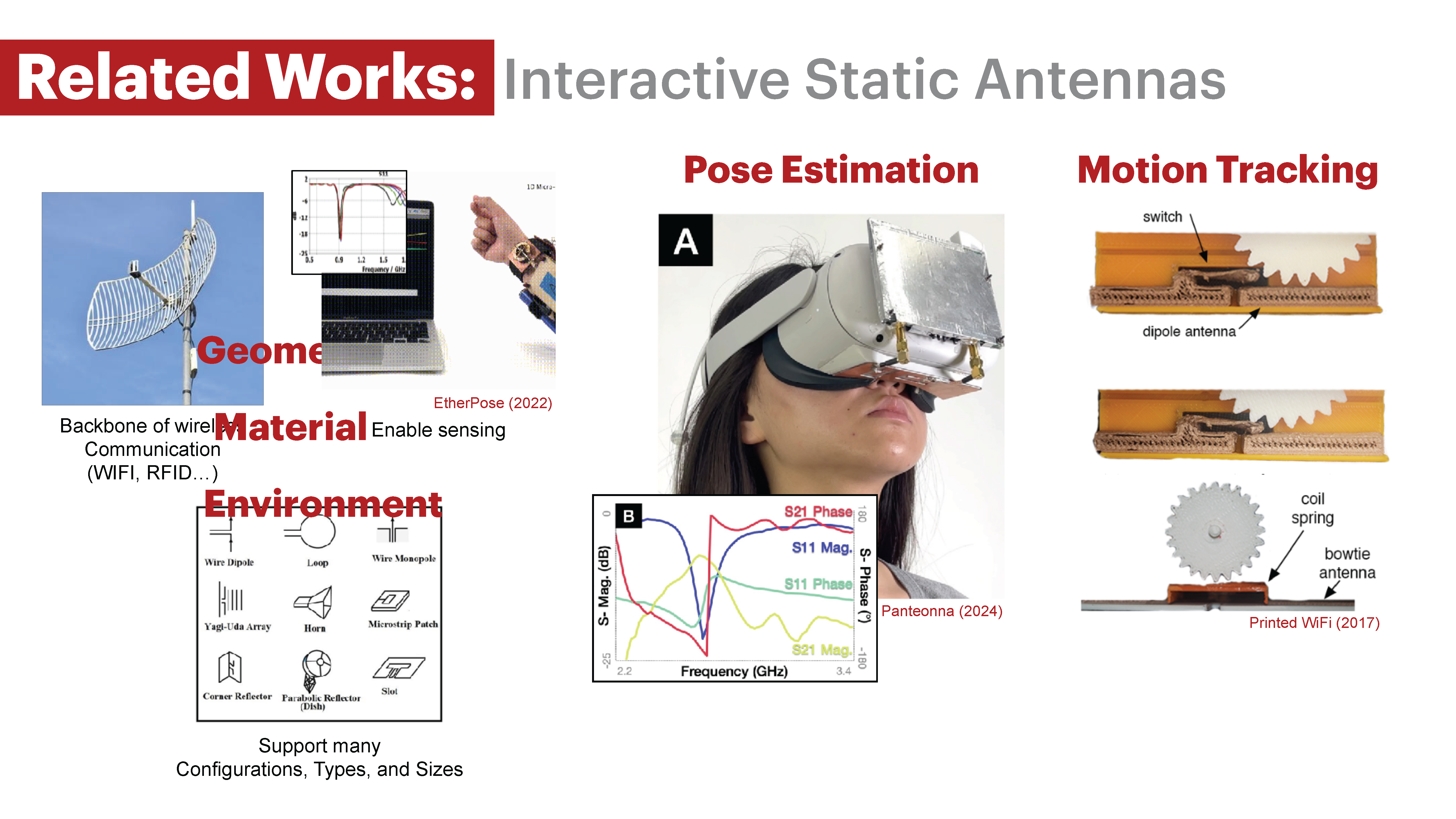
In recent years, the HCI community has demonstrated how antennas can be integrated into interactive systems. These systems enable applications such as gesture recognition, energy transfer, and mechanical motion sensing. For example, researchers have shown how antennas can recognize human gestures and translate them into movements of an avatar in XR applications [22 , 23], integrated antennas into wearable devices for energy harvesting [33], and illustrated how antennas can be used as encoders for mechanical motion tracking [18]. The function and performance of the antennas are largely dependent on the antenna’s ability to efficiently radiate, which is determined by several factors like the antenna’s geometry [31], material [34], and operating environment [15].
Traditionally, antennas are designed with fixed geometries, i.e., a single geometric configuration corresponding to fixed Radiofrequency (RF) properties. For example, the patch antenna designs in PrintedWifi [18] track mechanical rotations, but they are static antennas with fixed resonant frequencies and radiation patterns. Although fixed geometry antennas are suitable for certain use cases, they are less effective for broader applications, such as environment-adaptive sensing [36], mode switching between data transmission and reception [7], and development of dynamic antennas that seam- lessly operate across a range of network protocols [29]. This limitation in static antenna capabilities highlights the need to design dynamic antennas that alter their radiation characteristics.
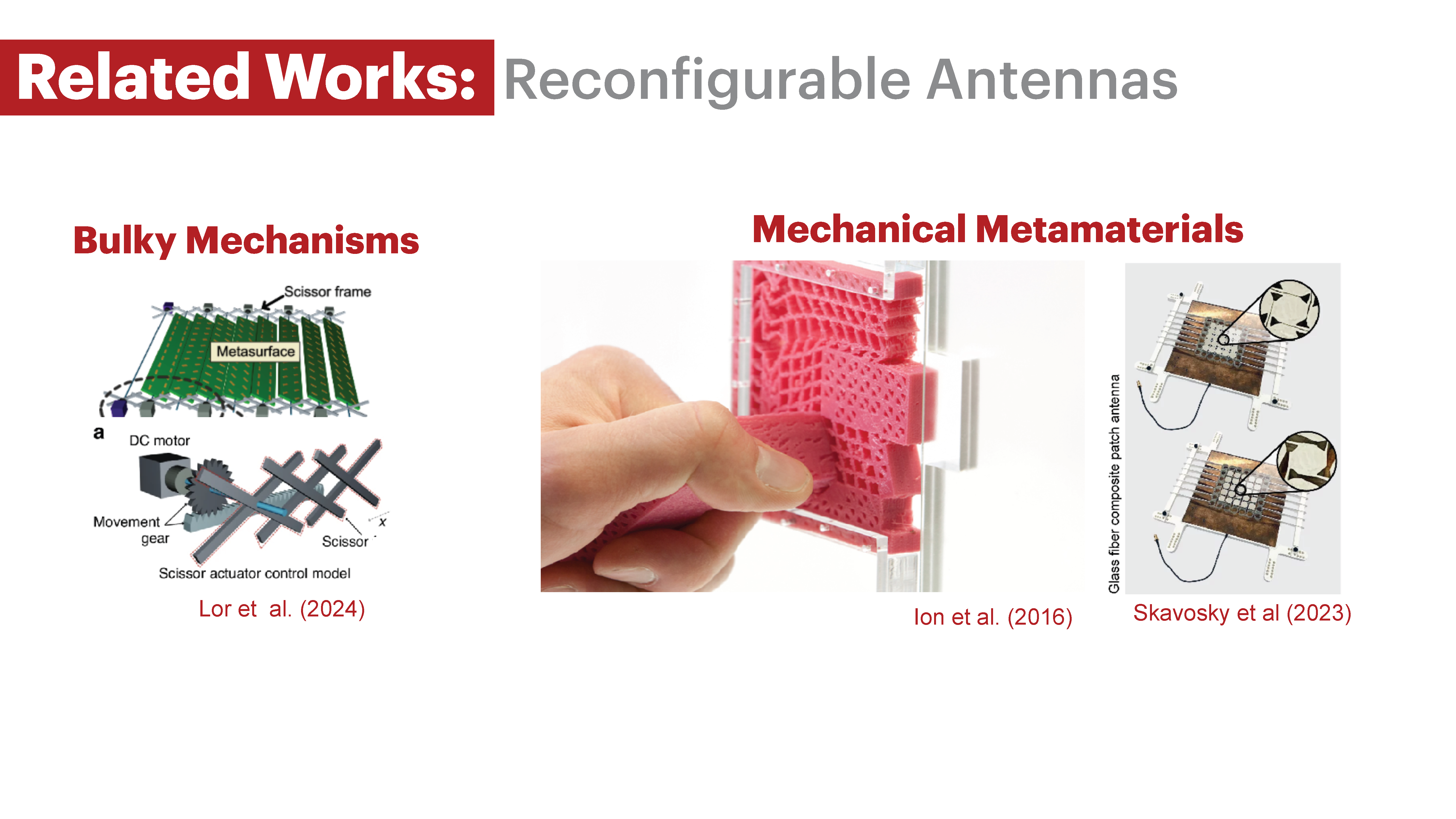
To address this, researchers developed reconfigurable antennas that can adjust their RF parameters while adopting a single antenna structure. One approach uses mechanical reconfiguration which relies on physically altering the geometry of an antenna to tune its function and performance. Such mechanically reconfigurable systems utilize actuators, like motors, to move assemblies of linkages [30], gears [30, 32] and ground planes [9].
However, actuation-based mechanical methods can quickly increase the mechanical complexity of reconfigurable antenna systems, especially if the designed antenna must support multiple motion primitives such as bending, expansion, and rotation. To address these limitations, we propose a mechanical building block structure that supports these motion primitives, while guaranteeing simplified designs for mechanically reconfigurable antennas.
Mechanical metamaterials are one flavor of building block structures that have been explored within HCI for various interactive applications [14 , 17]. These metamaterials can be programmed to adopt different physical shapes [25] and support multiple motion primitives such as bending, expansion, and rotation. Researchers have even leveraged these structures to build mechanically reconfigurable antennas, eliminating the need for bulky multi-component mechanical assemblies. Existing work have primarily explored how incremental compressions for a single mechanical metamaterial structure affects resonant frequency and radiation pattern, without exploring how changes in geometry or other interactions, like rotation, influence antenna behavior. [3, 37]. In other words, current metamaterial antenna systems do not utilize the full expressive power of metamaterials. Metamaterial structures have the potential, through reversible changes in their geometric state, to be designed as reconfigurable antenna that adapt to various interaction paradigms. Thus, the design and fabrication of programmable metamaterial antennas and how they can be applied to various primitive interactions remain under-explored.
In this paper, we explore the design, implementation, and evaluation of a mechanically reconfigurable patch antenna based on metamaterial structures. We demonstrate how this type of metamaterial structure can dynamically adjust the antenna frequency by changes in (1) antenna geometry length, (2) presence of dynamic holes \& slits, and (3) multi-state pattern configurations. \added{Despite these structural modifications, the Meta-antenna retains its fundamental capabilities as an antenna, capable of its original functions such as wireless communication and sensing.} We also contribute a design tool that enables users to generate reconfigurable metamaterial antennas. Additionally, we provide five technical evaluations covering our fabrication technique, the electrical durability of the Meta-antenna structures, and our design tool's simulation results. We also introduce three example applications on adaptive electronic devices, smart furniture, and tangible user interfaces that showcase how our proposed reconfigurable metamaterial antennas can be applied to everyday use cases.
In summary, we make the following contributions::
- Meta-antenna, a mechanically reconfigurable metamaterial antenna geometry that acts as a building block for reconfigurable antenna systems
- an Ansys-based Meta-antenna construction and simulation tool and Python-Arduino code template for Meta-antenna sensing-based interactions
- a fabrication pipeline for constructing mechanically and electrically durable Meta-antenna structures
- five technical evaluations on the electrical durability and fabrication method of Meta-antenna
- three applications including smart home systems, adaptive electronic devices and tangible user interfaces.
META-ANTENNA: SENSING AND DESIGN PRINCIPLES
Meta-antennas are mechanically reconfigurable antennas that are engineered to take on specific configurations. The key idea is to integrate the antenna into a mechanical metamaterial that can reconfigure the antenna properties by deforming the antenna geometry. In this section, we first provide background on the antenna radio-frequency properties we aim to reconfigure, then provide an overview of our Meta-antenna structure and design criteria.
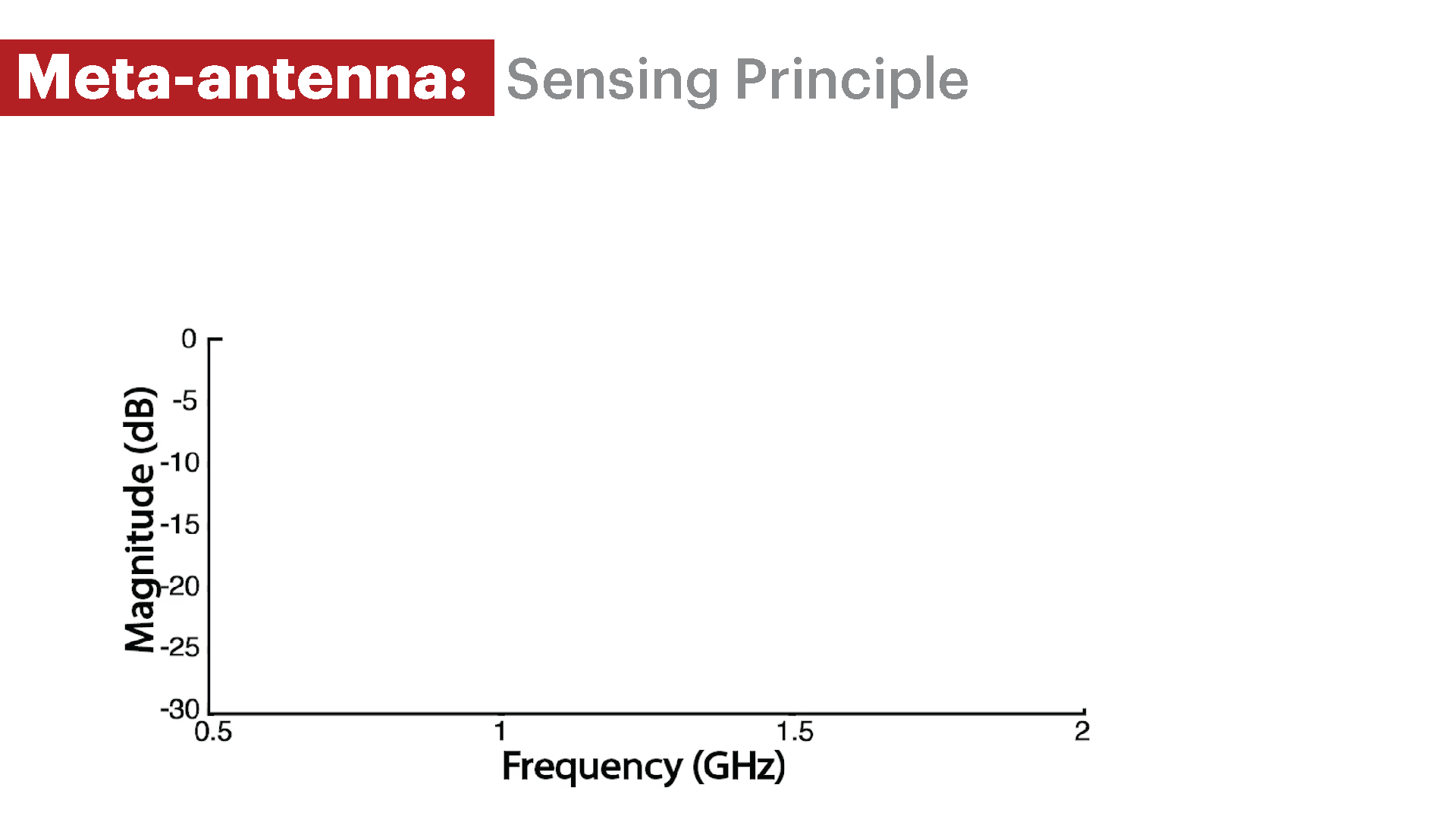
Sensing Principle Meta-antennas are frequency reconfigurable antennas. Mechanically deforming the antenna structure shifts its resonance frequency,i.e. the frequency at which it resonates or is the least lossless at, shifts. The amount of power that the antenna loses or transmits as a function of frequency is denoted as the antenna’s return loss, measured in decibels (dB). The more negative this dB value is, the less lossy the antenna is. For our Meta-antenna frequency reconfiguration to be significant we set two cut-off values based on literature: (1) a cut-off value for the antenna return loss magnitude, (2) a cut-off value for the percentage change in resonance frequency.
SENSING PRINCIPLE
Meta-antennas are frequency reconfigurable antennas. Mechanically deforming the antenna structure shifts its resonance frequency, i.e. the frequency at which it resonates or is the least lossless at, shifts. The amount of power that the antenna loses or transmits as a function of frequency is denoted as the antenna's return loss, measured in decibels (dB). The more negative this dB value is, the less lossy the antenna is. For our Meta-antenna frequency reconfiguration to be significant we set two cut-off values based on literature: (1) a cut-off value for the antenna return loss magnitude, (2) a cut-off value for the percentage change in resonance frequency.
Antenna Return Loss Cut-off: The cut-off we use for determining whether a resonant frequency is worth considering or not is -10db. This value corresponds to a power loss of less than 10%, and is an acceptable cut-off for antenna return loss based on literature.
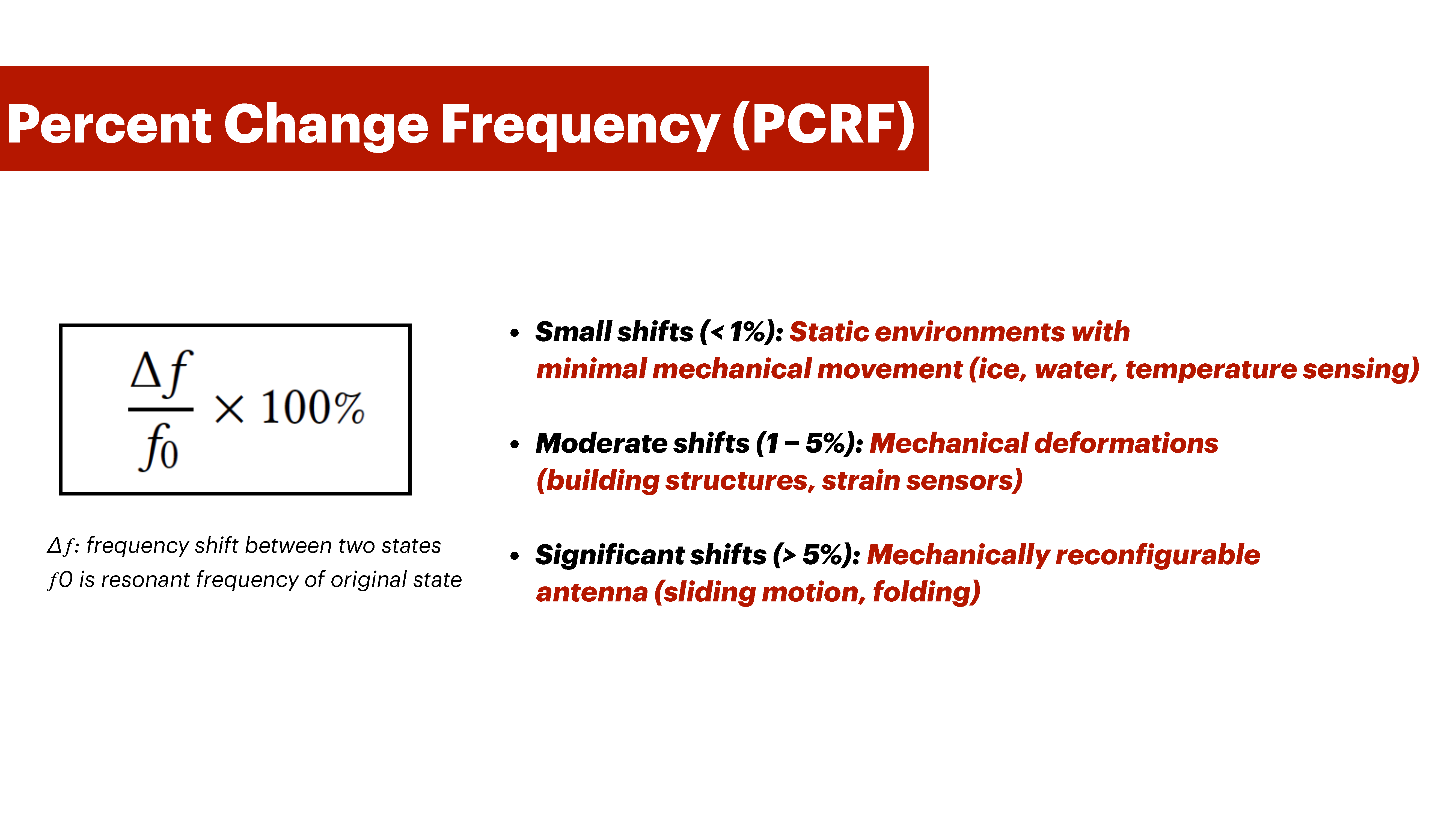
Antenna Percentage Change in Resonance Frequency: Percentage change in resonance frequency (PCRF) measures how much the Meta-antenna's resonant frequency shifts upon reconfiguration.
The PCRF is given by:
$$\frac{\Delta f}{f_0} \times 100\%$$
where \( \Delta f \) is the frequency shift and \( f_0 \) is the original resonant frequency.
Based on literature, we break down frequency shifts to three categories:
- Small shifts (< 1%): Ideal for static environments with minimal mechanical movement. Examples include antenna for ice and water detection or temperature sensing.
- Moderate shifts (1–5%): Suitable for mechanical deformations of building structures or as strain sensors in flexible antenna.
- Significant shifts (> 5%): Suitable for mechanically reconfigurable antenna like sliding motion antenna, and folding mechanical antenna.
For Meta-antennas, we set the percentage shift to be no less than 1%, as these shifts are compatible with mechanical motion.
Meta-antenna relies on resonant frequency shifts caused by deformation as a basis for its sensing principle. To determine the antenna's resonant frequency, we sweep our antenna through a frequency range of 500 MHz to 6.3 GHz and record the frequencies where the -10dB cut-off occurs. When the antenna deforms into a new geometric configuration, the resonant frequency shifts from the previous configuration. For a shift to be considered significant in mechanical applications, it must meet our predefined PCRF criteria.
META-ANTENNA DESIGN PRINCIPLESMotivated by research on reconfigurable antenna design principles and metamaterial structures, we developed the following design criteria. Our criteria are segmented into (1) mechanical design goals and (2) radio-frequency design goals. For the mechanical design goals, we identify the following for our meta-antenna structures:
- DG1: the structure mechanically deforms and the deformation is programmable
- DG2: the structure is mechanically and structurally stable
- DG3: the structure accomodates different user interaction primitives such as compression, bending, and rotation
We use the frequency shift categorization and return loss cut-off we introduced in Section Sensing Principle to inform our radio-frequency criteria for Meta-antenna based sensing:
- DG4: the structure has at least one resonant frequency that is within the acceptable return loss cut-off (≤ -10dB)
- DG5: the structure's mechanical deformation results in moderate to significant change in the antenna's frequency (PCRF > 1%)
Based on these design criteria, we chose the following metamaterial and antenna structures:
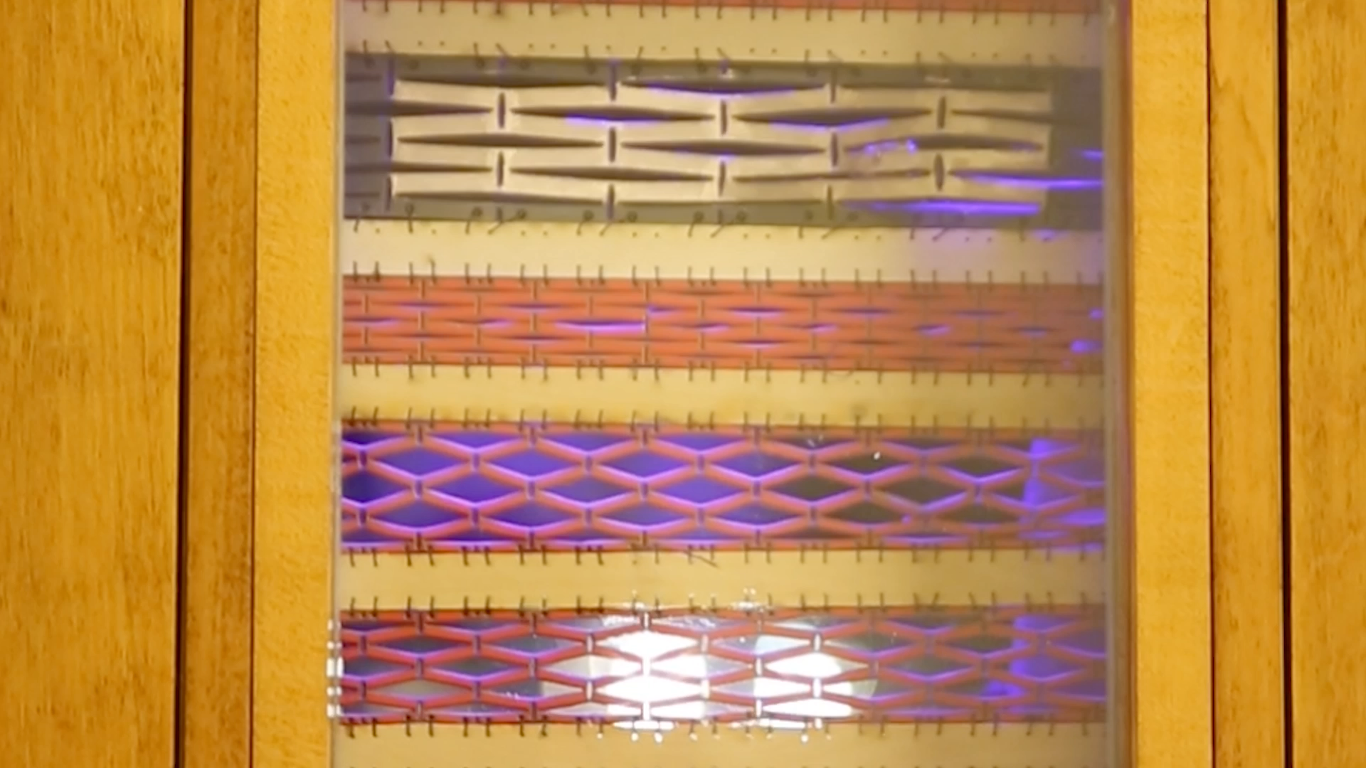
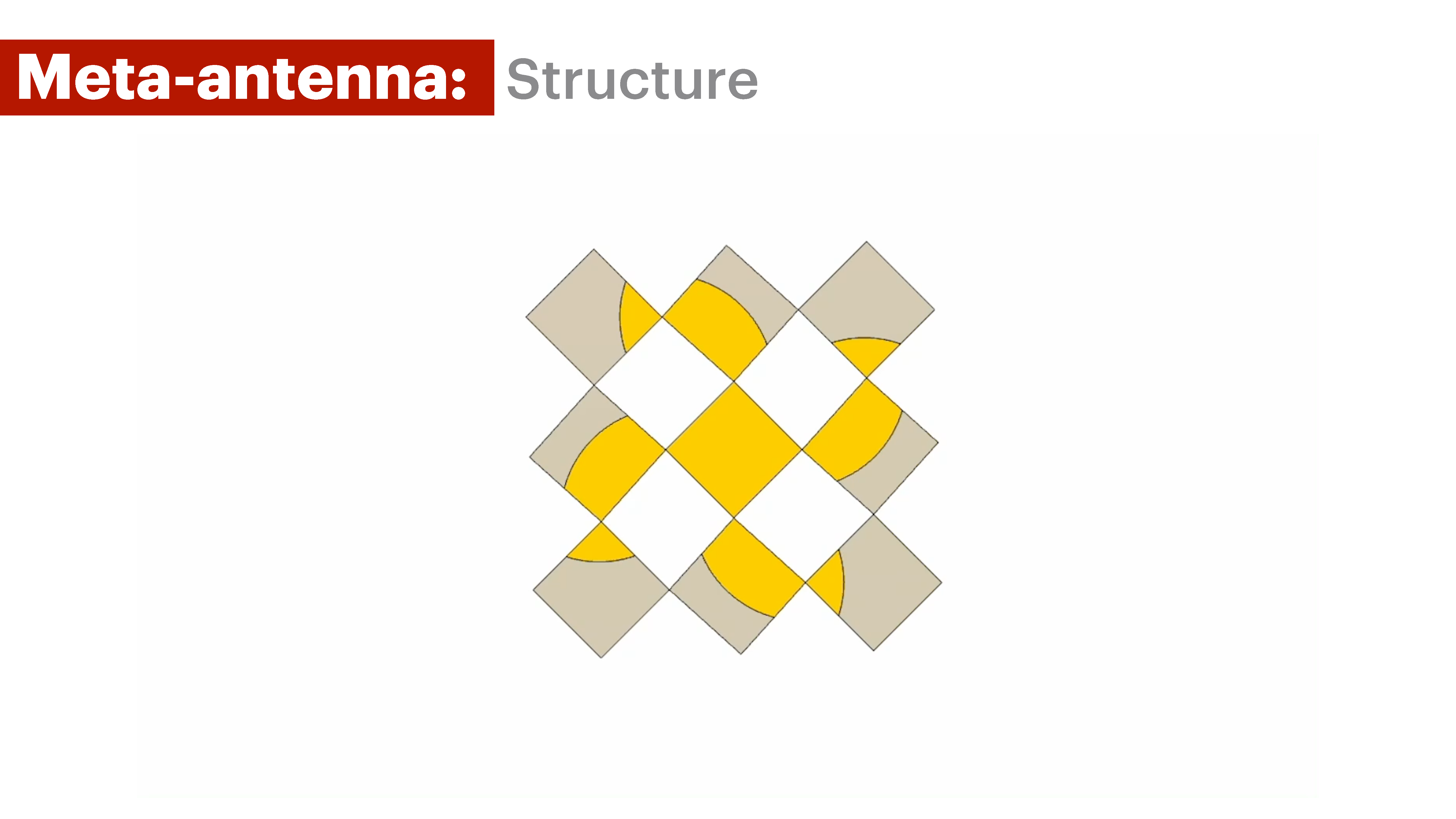
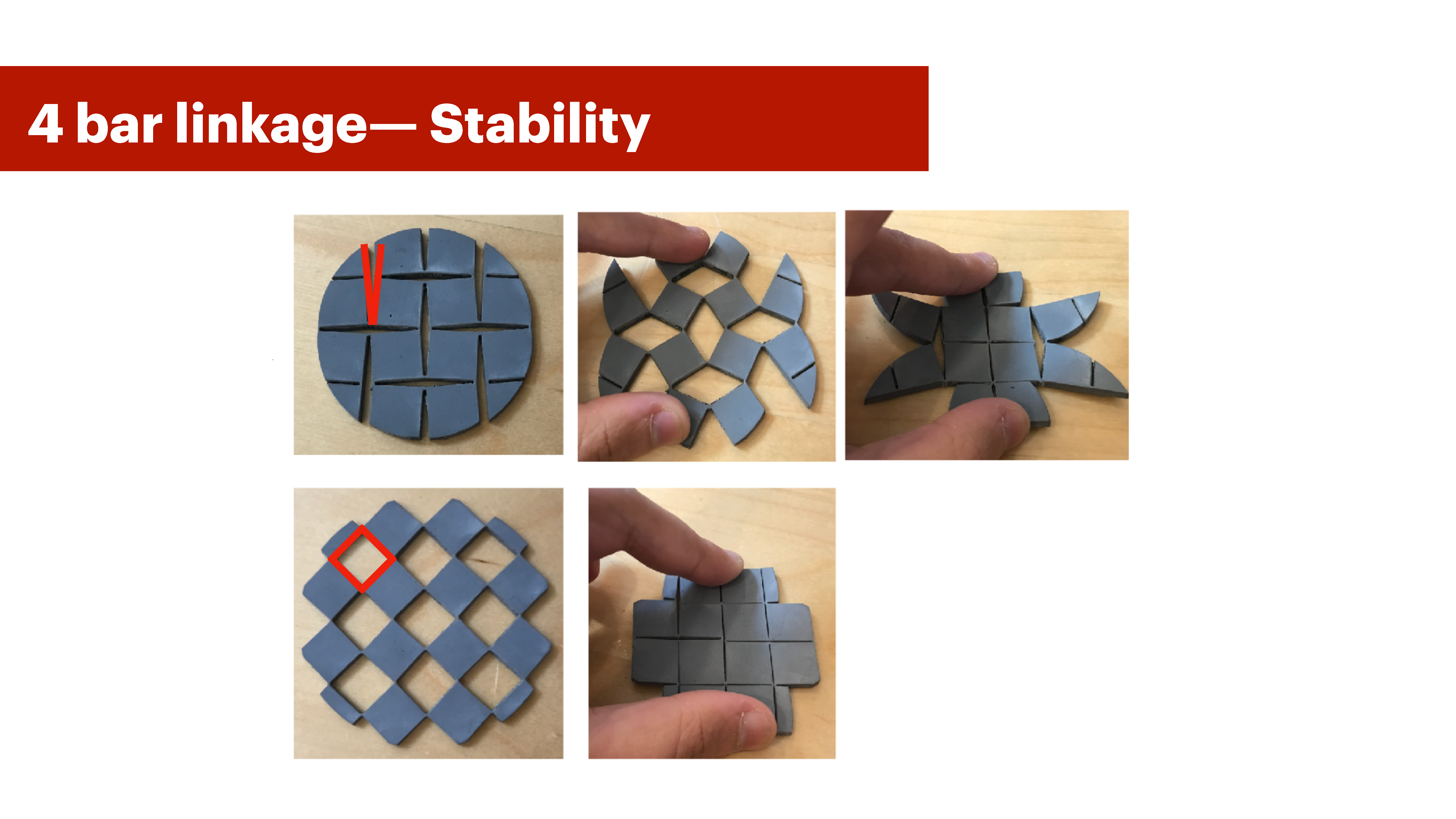
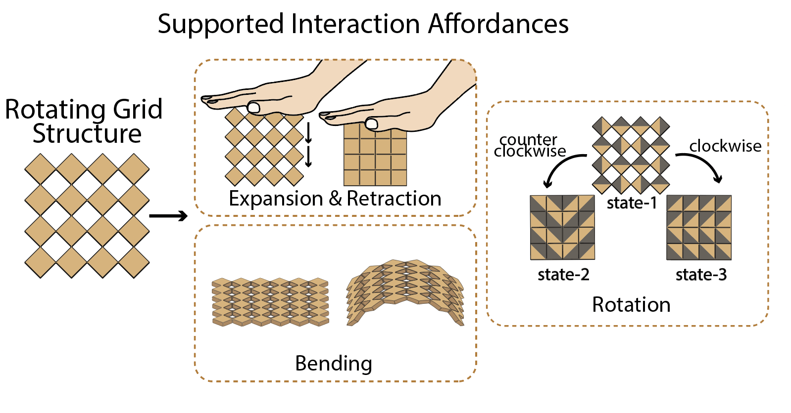
Metamaterial (Kirigami Auxetic Structures): To meet our design goals, we chose kirigami auxetic metamaterials. These metamaterials comprise patternable cells with periodic cut designs that allow them to achieve different deformations through compression, bending, and rotation when deployed (DG3) (Figure 2). The connection point between cells creates a four-bar linkage which makes the structure mechanically stable (DG2). This allows cells to rotate clockwise and counter-clockwise and take on specific configurations that create different deformations (DG1, DG3).
Antenna Type (Patch Antennas): For the antenna, we chose patch antennas, which are a planar type of antenna that can be patterned onto the previously selected metamaterial cell structures. Since our metamaterial geometries consist of planar cell structures, planar antennas are particularly suitable to be integrated onto the cell faces. As our metamaterial structure deforms, the geometry of the patch antenna changes, resulting in different antenna radiation characteristics (DG4, DG5).
Next, we outline how changing specific geometric dimensions in a patch antenna influences its radio-frequency (RF) properties.
PATCH STRUCTURE AND PROPERTIES
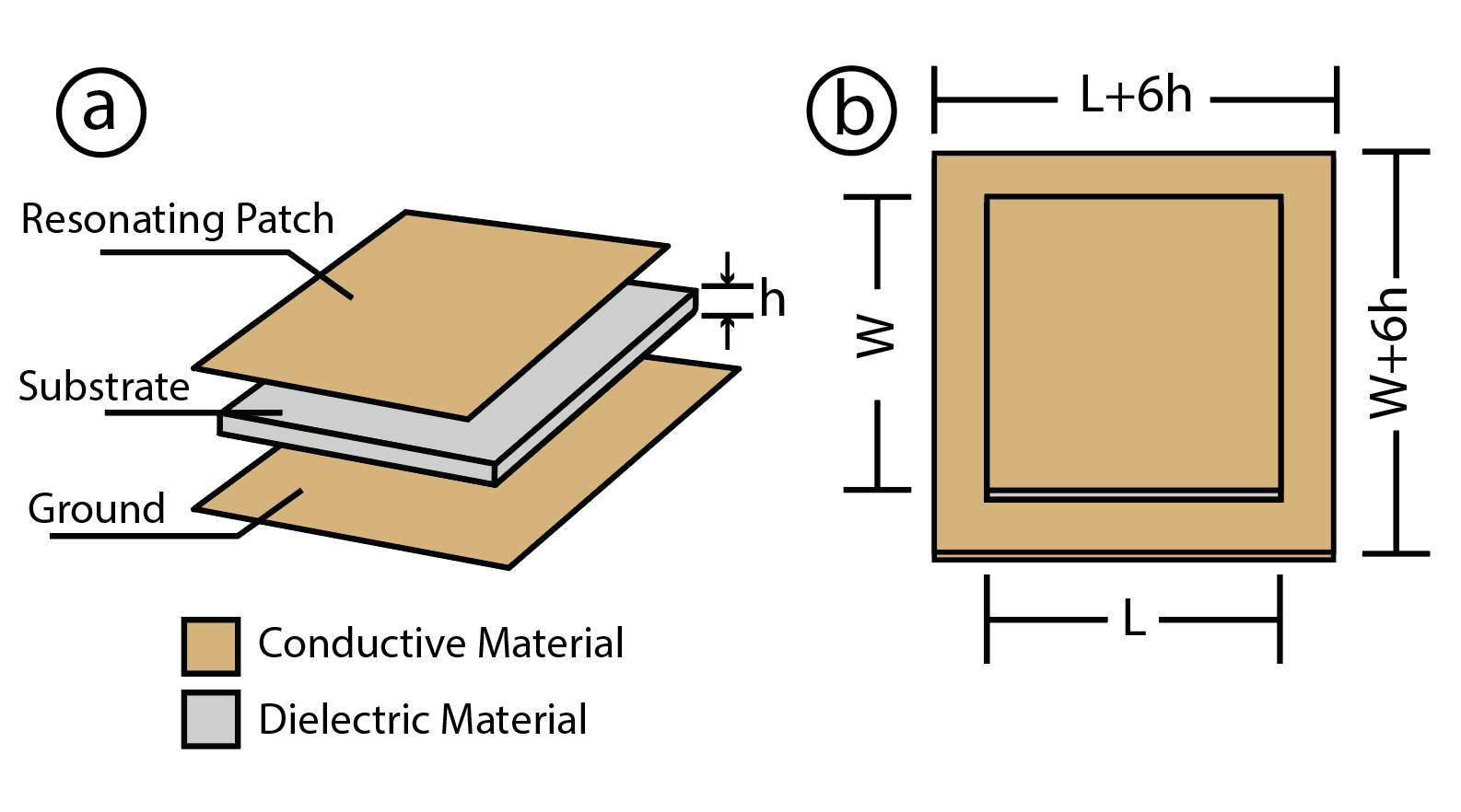
Traditional patch antennas consist of three layers: a dielectric layer sandwiched between two conductive layers. As shown in Figure 3, these layers include the top conductive layer (resonating patch), the dielectric layer (substrate), and the bottom conductive layer (ground plane). Because of this simple structure and material composition, patch antennas can be easily fabricated on both 3D printers and laser cutters.
The antenna's RF properties are affected by: (1) the shape of its patch, (2) its length, and (3) the presence of holes and slits.
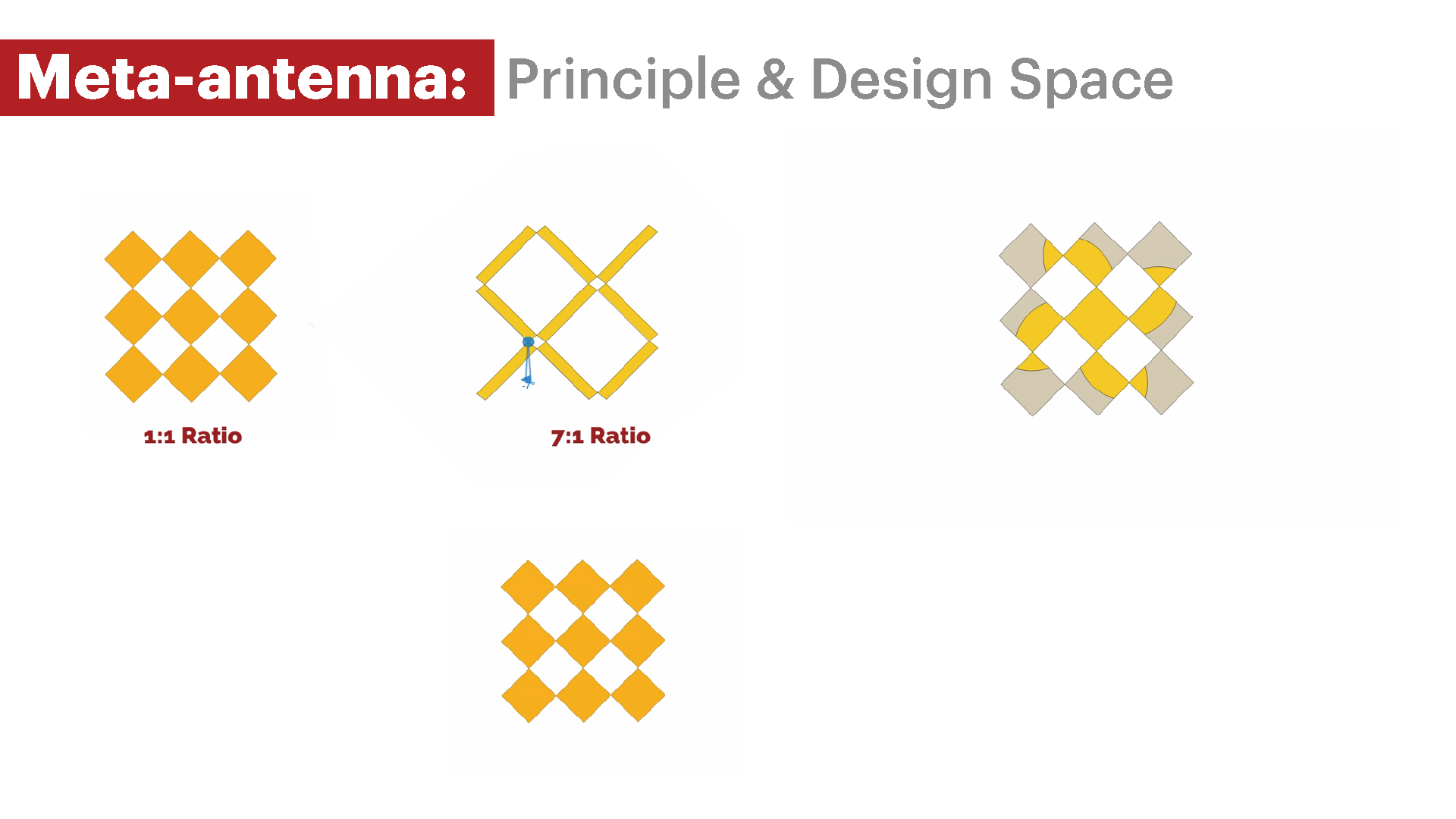
Antenna Patch Shape: Patch antenna properties are significantly impacted by the overall shape of the antenna's patch, i.e., the pattern of the resonating patch design on the substrate. For example, Figure 4 shows a bowtie vs a square antenna integrated into the same square structure. Different antenna patch patterns yield distinct resonance frequencies \cite{antennashapepattern}. Therefore, an antenna that results in three different patch patterns upon rotational deformation (Figure 4) yields different resonance frequencies even though it is embedded in a single fabricated structure.
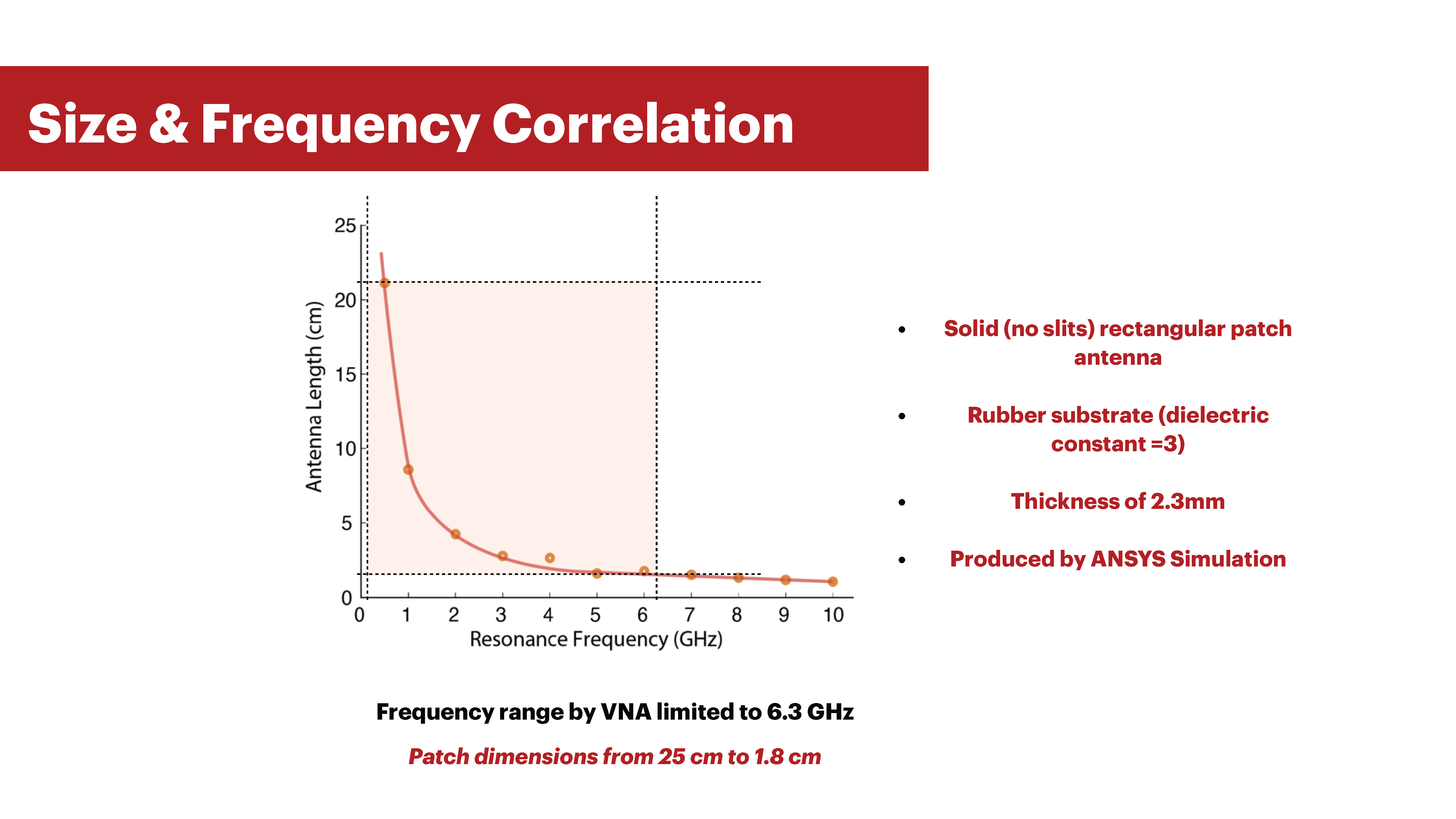
Antenna Length: The length of the antenna refers to the longest side of the patch antenna substrate. The length of a patch antenna has a significant impact on its RF properties. The greater the antenna length, the lower the resonating frequencies. By integrating the patch antenna into a meta-material, we can significantly change its length as the metamaterial deforms (Figure 5).
Presence of Holes and Slits: The introduction of slits and holes into a patch antenna can also either shift its resonance frequency or generate multiple resonant frequencies within a specific range. This is in contrast to a solid patch antenna. Since our metamaterial structure is an auxetic kirigami geometry with cut patterns, it intrinsically introduces small slits into the antenna when it retracts, and larger holes as it expands (Figure 2) ).
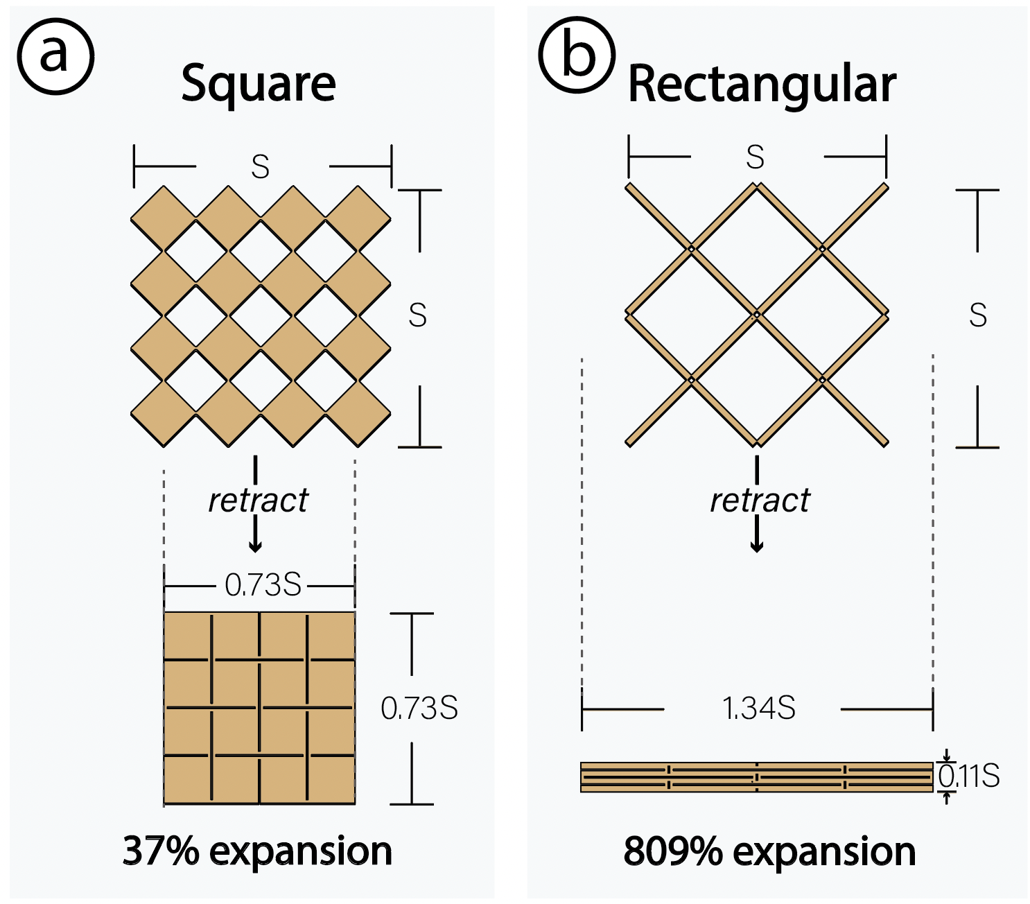
Figure 5: The expansion rate of a Meta-antenna refers to the change in size between its retracted and expanded states. (a) shows how an SxS sized square antenna expands to 37%, while (b) shows an expansion rate of 809% for a rectangular Meta-antenna with a 13:1 length to width ratio.
In summary, to ensure that our metamaterial structures meet our design goals, we opted for a rotating grid structure because it (1) can achieve beyond 222% reported change in length \cite{kirigamiauxeticstretch2017} (DG1) (2) can rotate to three different configurations and thus result in different antenna patch shapes across these rotational configurations (DG1, DG3), and (3) is structurally stable since the hinges between the cells of the structure form a four-bar linkage mechanism (DG2).
DESIGN PARAMETERSIn this section, we discuss key design parameters related to the construction of Meta-antenna geometries. We explore the different Meta-antenna states, how Meta-antenna expansion rate can be tuned, and the effects of Meta-antenna unit cell density on its structure. The goal of this section is to establish the effect of tuning these design parameters on Meta-antennas both mechanically and with respect to resonance frequency
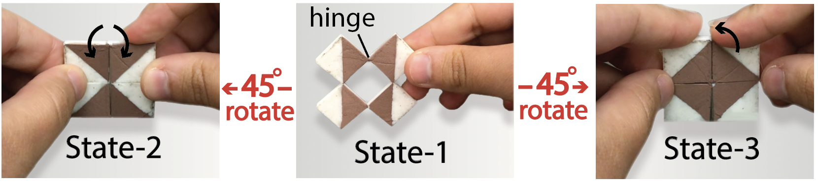
Antenna States : Antenna states refer to the different geometrical configuration that a Meta-antenna assumes upon its deformation. Meta-antennas have three states that they deform into: an expanded state (State-1) and two retracted states (States 2 and 3) as shown in Figure 4. A retracted meta-antenna refers to a deformed structure with the unit cells closely packed (i.e., no gaps), whereas an expanded meta-antenna means the structure is spread out, creating holes between the unit cells (Figure 2). The initial state that the antenna is fabricated in affects the mag- nitude of motion needed to reach other states. If the user fabricates the meta-antenna in its expanded state (State-1), the meta-antenna cells only need to move 45◦ clockwise or counter-clockwise to reach the other two states. However, if the user fabricates the antenna in its retracted State-2, the meta-antenna cells go through a 90◦ rotation in order to reach State-3, which adds more strain on the hinges connecting the unit cells (Figure 4). In summary, we recommend designing Meta-antennas in their expanded state if the goal is to trigger changes through retraction, with two possible configurations (clockwise and counterclockwise). If the aim is to simply expand or retract the structure to trigger changes, we recommend designing antennas in their retracted state. Finally, the change of states affects the antenna’s resonant frequency since the antenna length changes, as well as the pattern as long as State 2 and 3 are non-identical (Figure 4).
Meta-antenna Expansion Rate : The expansion rate of a Meta-antenna refers to the maximum amount the antenna moves between State-1 and States 2-3 (Figure 5). The ratio of the unit cell’s length and width in a Meta-antenna structure affects its expansion rate. The relationship between the expansion rate of the Meta-antenna structure and its unit cells’ length to width ratio is defined as:
\[ \text{Expansion Rate} = \frac{W_{\text{exp}} - W_{\text{ret}}}{W_{\text{ret}}} \] Where \( W_{\text{exp}} \) is the expanded width and \( W_{\text{ret}} \) is the retracted width of the system.
The full expansion rate formula we derived is as follows:
\[ \text{Expansion Rate} = \left( \left( W_{\text{ret}} - n_w \left( \frac{s}{2} \right) \right) \left( \alpha (1 + r) - 1 \right) + (n_w - 1) \left( s - \alpha H \right) - \frac{n_w s}{2} \right) \cdot \frac{1}{W_{\text{ret}}} \]
Where \( \alpha = \frac{1}{\sqrt{2}} \), \( r = \frac{u_L}{u_W} \) is the ratio of unit length to unit width, \( n_w \) is the number of unit cells along the width (Meta-antenna \( y \)-density), \( s \) is the antenna slit size, and \( H \) is the hinge size.
This equation tells us that the smaller \( r \) is, the smaller the expansion rate for the structure. Conversely, a larger \( r \) results in a higher expansion rate for the antenna width. The smallest expansion rate, for a fixed number of units with \( u_L > u_W \), occurs at \( r = 1 \), indicating a square structure. Otherwise, if \( u_W > u_L \) the ratio flips as shown in Figure 6-b.
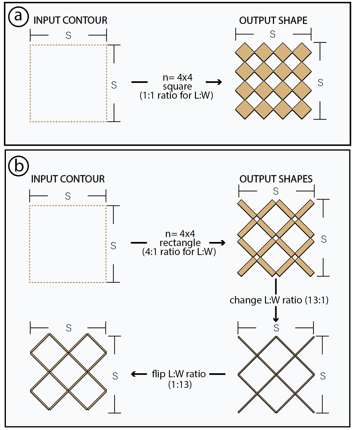
Figure 5: The expansion rate of a Meta-antenna refers to the change in size between its retracted and expanded states. (a) shows how an SxS sized square antenna expands to 37%, while (b) shows an expansion rate of 809% for a rectangular Meta-antenna with a 13:1 length to width ratio.
Meta-antenna Density : Meta-antenna density refers to the total number of unit cells by row and column in a given area (nxm). For example, a 3x2 Meta-antenna density refers to a structure with 3 unit cells per row and 2 unit cells per column. For a given Meta-antenna size, the minimum Meta-antenna density is 2x1 or 1x2. Increasing the density causes the the Meta- antenna structure to become more rigid against compression thereby increasing the amount of force required to actuate the antenna. The proportional relationship is between Meta-antenna density and force of actuation is as follows:
\[ F \propto \frac{n}{D} \]
Where \( n \) is the number of Meta-antenna units in the \( x \) or \( y \)-direction, and \( D \) is the width or length of the Meta-antenna.
However, we note that while increasing Metantenna density increases the compression force, it also makes the structure easier to bend. In terms of antenna resonant frequency, the higher the density of a Meta-antenna in its State-1, the less its frequency response deviates from that of a solid antenna patch of the same size.
META-ANTENNA EDITOR
To help users design and simulate Meta-antenna geometries, We built a Meta-antenna design suite editor for Ansys HFSS (High Frequency Simulation Software) through the Ansys App Builder and ACT Toolkit. In this section, we present the main functions of our editor.
Defining the Size of the Metamaterial Patch : The user begins by inputting the width and length of the Meta-antenna patch size (mm). Based on solid patch antenna designs, we set the maximum and minimum patch dimensions in the editor to be 25 and 1.8 cm, so that the resulting resonance frequency will fall between 500MHz to 6.3GHz. This range is determined by the sensing range of our LiteVNA, the device we use to measure antenna resonance frequency. The relationship between patch size and resonance frequency is shown in Appendix A.
Choosing Substrate Material Thickness: The user then specifies the thickness of the substrate (dielectric). Based on the userspecified patch size and substrate thickness, the editor automatically calculates the size of the ground that minimizes fringing effects around the antenna, to be 𝑊 + 6ℎ for width and 𝐿 + 6ℎ for length, where 𝑊 is the width, 𝐿 is the length, and ℎ is the height of the Meta-antenna substrate.
Unit Cell Length to Width Ratio : The user then inputs the length and width ratio of the unit cell as integer values. With the length & width values and previously input substrate thickness, the editor performs an automatic design check for potential unit cell bending effects and generates design recommendations.
Specifying the Number of Units (Meta-antenna Density) : Next, the user defines the number of units, i.e. Meta-antenna density, in the x and y axes.
Loading DXF Pattern : By default, the Meta-antenna design suite uses a rectangular or square pattern for the patch shape. Users can also load a custom DXF file for the resonating patch’s pattern. Choosing Generated State : Next, the user selects which Meta-antenna state, from the three available, they would like to run the simulation in.
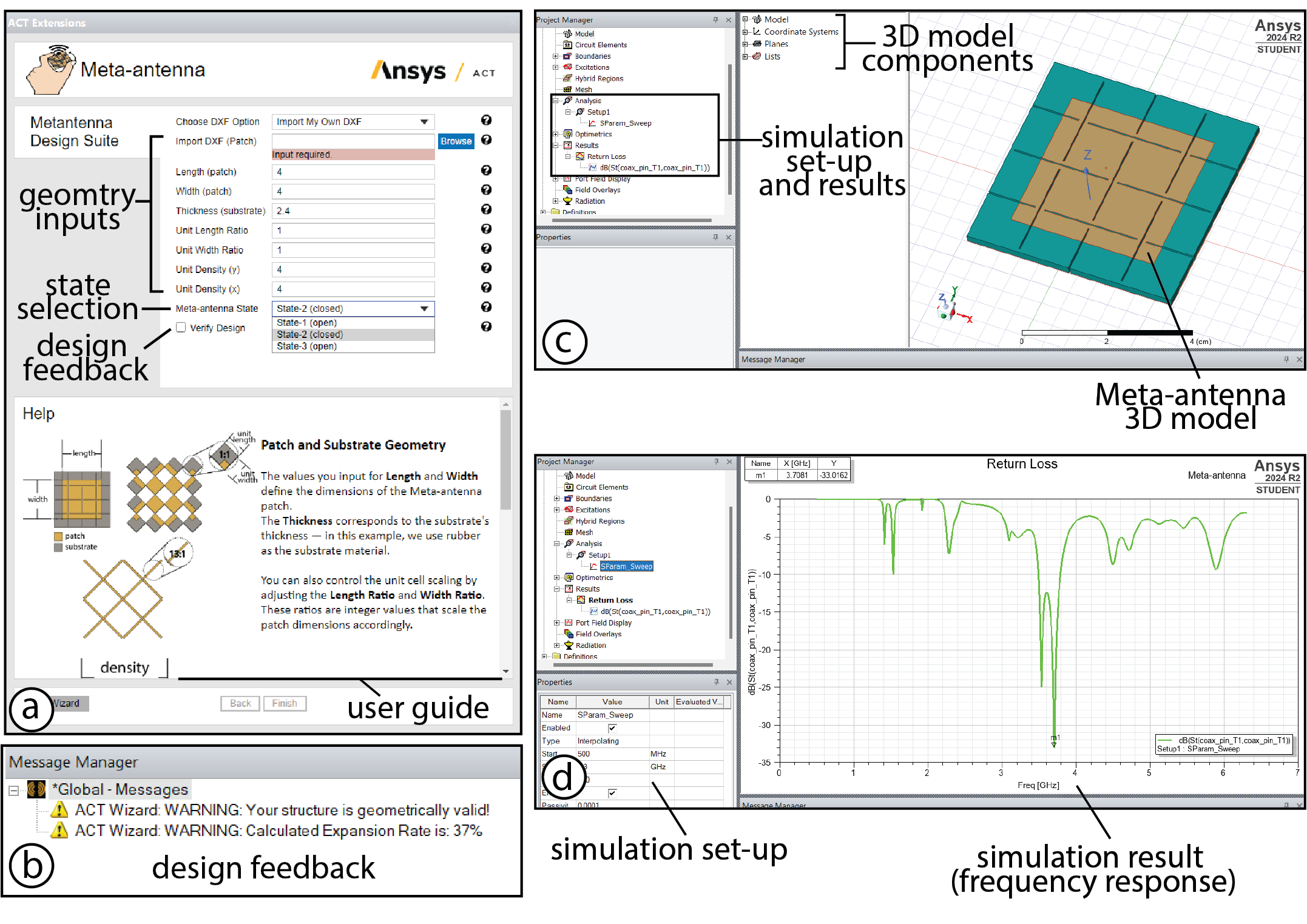
Verifying the Design Inputs : The user then clicks on the “Verify Design” check-box to see if their input is valid for a Meta- antenna geometry. If the user’s design parameters do not meet the mechanical constraints of the system, the edi- tor suggests fixes for the geometry. The Meta-antenna editor also calculates the expected expansion rate as seen in Figure 7-b.
Generating the Metantenna Structure: After inputting all parameters and verifying the design, the user clicks the “Finish” button to generate the Meta-antenna structure. Based on the gener- ated Meta-antenna, the editor automatically picks the geometrically optimized SMA probe (connector used to measure the antenna fre- quency) location that is both the least lossy and geometrically valid.
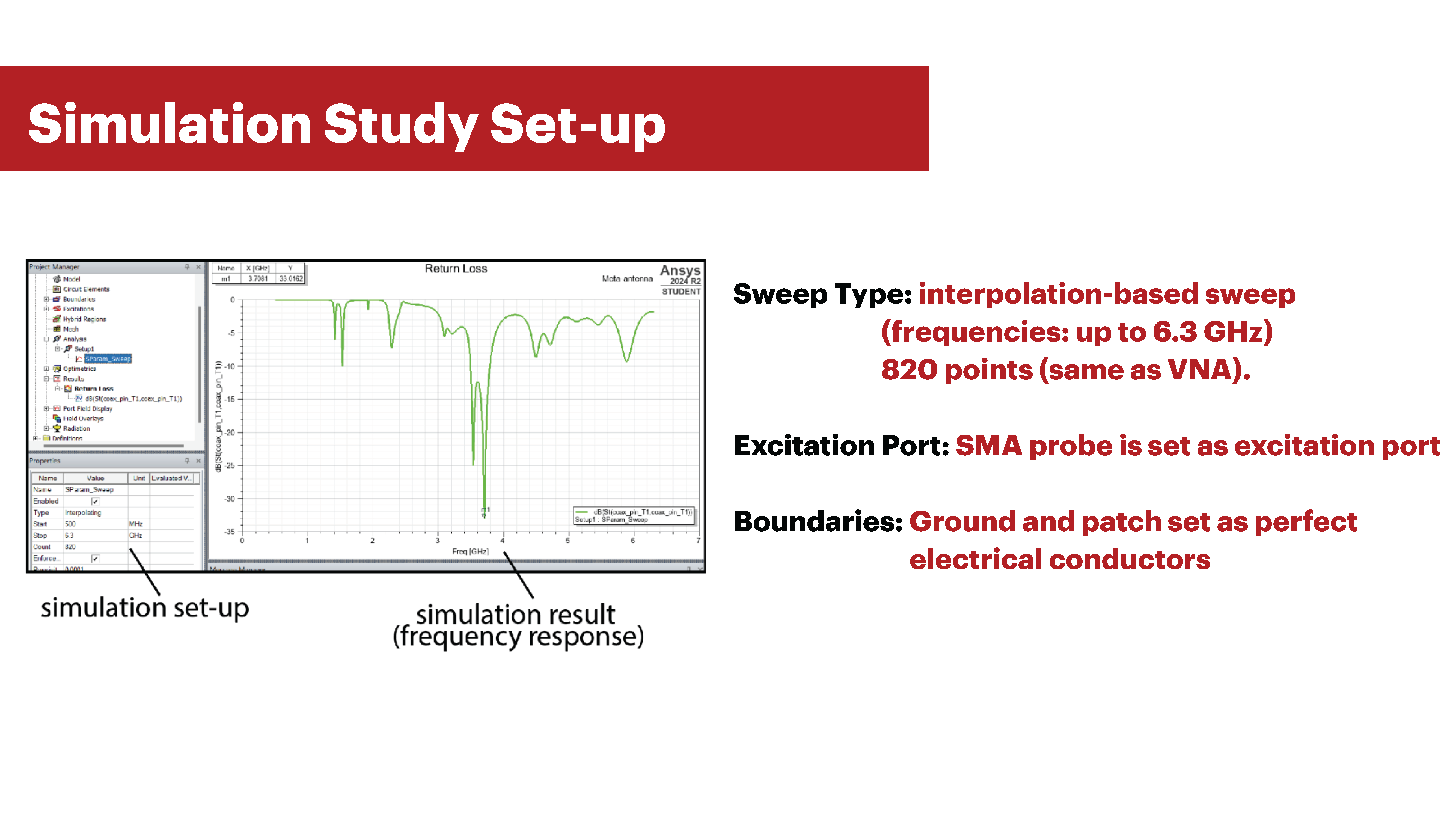
Running the Simulation: Meta-antenna automatically sets up a “return loss” simulation study for the user. To run the return loss simulation, the user clicks the “run study” button in the Ansys toolbar to run the simulation. Our editor then runs the study by performing an interpolation-based sweep through frequency values of 500MHz to 6.3 GHz with 820 points. The SMA probe is set as the excitation port, and the ground and patch are set as perfect electrical conductor boundaries.
Displaying Simulation Results: To display the results of the simulation as a graph of the return loss magnitude (dB) versus frequency (GHz), the user can click results tab -> return loss. The user can also export this data to CSV format
Exporting Files: Finally, the user exports the generated Meta-antenna 3D model in obj format.
META-ANTENNA FABRICATION
We fabricate our Meta-antennas by laser cutting the metamaterial geometry, followed by applying conductive spray paint to form the ground and patch layers. In this section, we highlight the steps taken to fabricate our Meta-antenna geometries and how we prepare them for their interactive applications.
Laser Cutting Metamaterial Geometry and Patch Antenna Mask
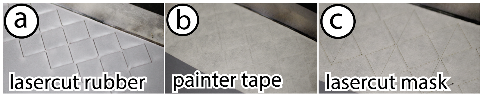
Figure 8: (a) Meta-antenna geometries are fabricated from lasercut rubber sheets. (b-c) the rubber sheets are masked with painter’s tape that is lasercut to the antenna’s patch pattern shape.
Fabricating Metamaterial Geometry and SMA Probe Location: We use lasercutting as our main fabrication method. To prepare for lasercutting, we convert the OBJ file from Ansys into a DXF file with CAD software. We laser cut off-the-shelf laser-cuttable rubber sheets for the main metamaterial geometry. Rubber is flexible and durable under repeated compressions, making it ideal for our Meta-antenna base interactions (DG2). We measured the dielectric constant of our rubber material on an LCR Meter (Keysight, E49808BL) to be 2.7 at 300kHz, which makes it suitable for our antenna frequency response. On our Universal laser cutter (PLS6.150D), we cut the rubber sheets with 100% power, 3.3% speed, and 200 PPI. We leave the cut rubber sheet inside the laser cutter for the next fabrication step. Besides cutting out the metamaterial geometry, this step also cuts out a hole for the SMA probe.
Fabricating Antenna Masks: To create the antenna patch pattern using conductive spray paint, we laser cut a masking layer that covers areas not meant to be spray-painted. To accomplish this, we cover the lasercut Meta-antenna geometry, while still inside the laser-cutter, with painters tape. For laser cutting the mask, we chose settings that cut the painter’s tape mask, but neither cut nor engrave the surface of the rubber. We laser cut the painter’s tape mask with 16% power, 100% speed, and 500 ppi. After cutting the mask, we remove the Meta-antenna geometry from the laser cutter.
Spraypainting Grounding Layer and Patch Antenna
Spray-painting the Grounding Layer: Next, we spray-paint the entire bottom of the metamaterial geometry with a copper-based conductive material using an airbrush (Master G233). We use MG-chemicals silver coated copper spray paint (843WB), which is highly conductive (5.3 × 10⁻⁴ resistivity). To ensure good coverage, we apply two layers (0.01778mm) of the spray paint, waiting 30 minutes between each layer to air dry.
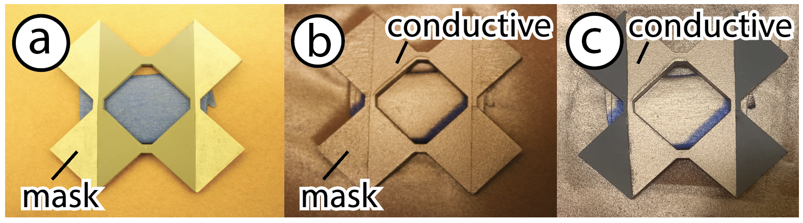
Figure 9: Meta-antenna patches are fabricated with conductive spray paint.
Spray-painting the Conductive Patch Pattern: Before applying the conductive spray paint to form the patch on top of the metamaterial geometry, we first remove the sections of masking tape covering the areas intended for conduction. We then spray-paint the exposed regions, following the same procedure used for the ground layer. After allowing the second conductive layer to dry for 30 minutes, we peel off the remaining masking tape from the rest of the structure.
Coating to Improve Electrical Durability at the Hinges
Coating the Meta-antenna: In the final step, we coat the hinges only of the Meta-antenna top and bottom surfaces with a flexible acrylic paint (PlaidFX Flexible Acrylic Paint) which can either be spray-painted or directly applied via paintbrush. We found that applying the coating improved the electrical connection durability of the Meta-antenna at the hinges (see Section 8.4). In fact, without applying the flexible coat, the Meta-antenna structure electrically breaks after only one compression. Before applying the coating, we manually mask out the region where the SMA probe connects on the top and bottom of the geometry to maintain the electrical connection of the SMA with the grounding and patch layers. After coating, we let the Meta-antenna air dry for 1 hour before using it.Meta-antenna Assembly
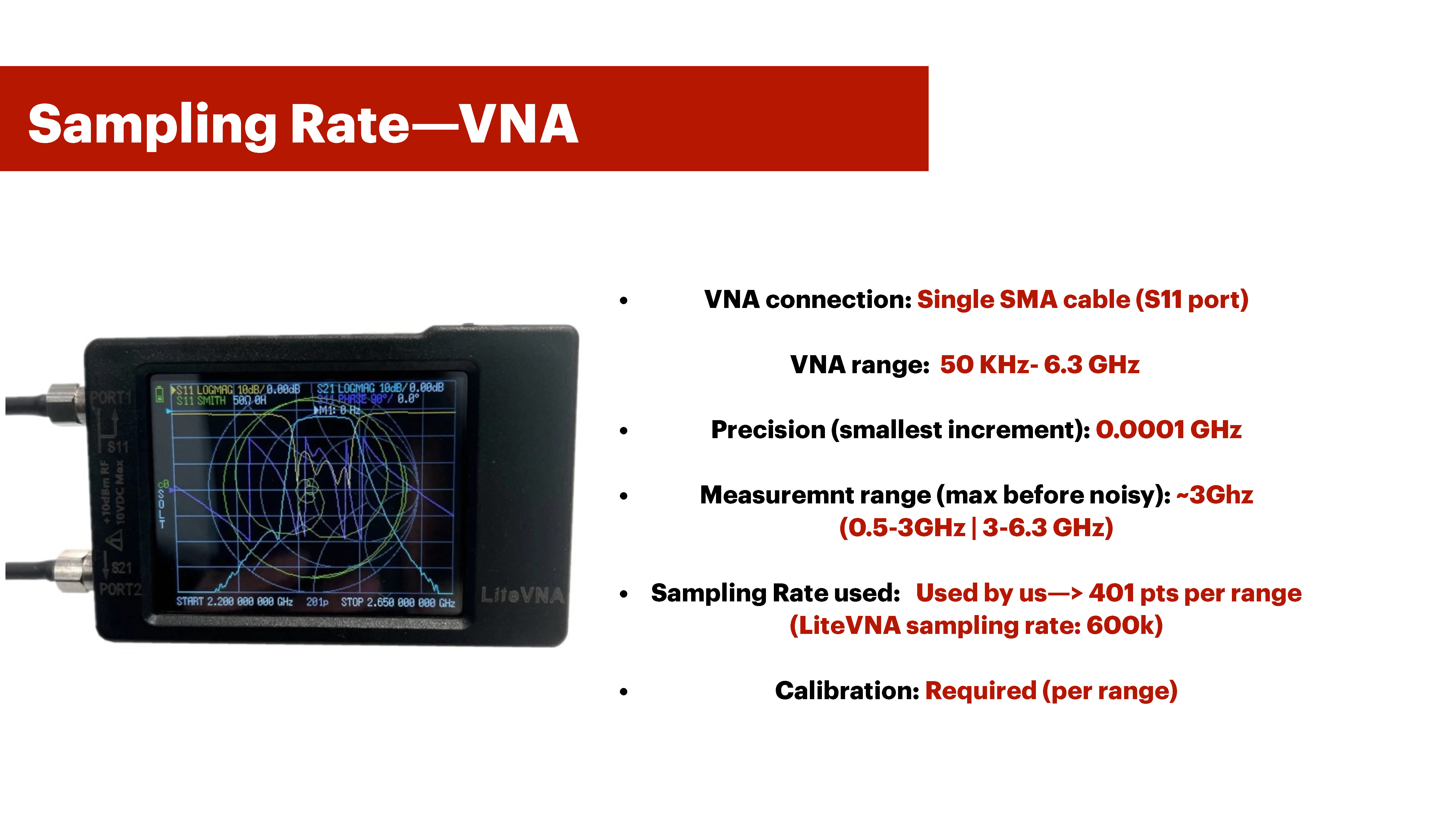
After fabrication, we connect our Meta-antenna structure to its supporting electronic components.Connecting SMA Probe to MetaAntenna Geometry: We choose a coaxial SMA probe (TAOGLAS CAB.058) that has a 50Ω impedance. We insert the SMA probe into the corresponding hole on our Meta-antenna. To secure the SMA probe in place, we use a two-part silver conductive epoxy (MG Chemicals 8331D) and apply it to the SMA probe location on the grounding and patch layers. We then cure the epoxy in an oven (70◦C for 15 minutes). Connecting Antenna SMA Probe to VNA for Resonant Frequency Based Sensing: To access the antenna resonance frequency, we connect the SMA probe to a Vector Network analyzer (VNA) via an SMA cable. We use a LiteVNA, which has a range of up to 6.3 GHz.
Connecting the Antenna-VNA to the Micro-controller: We connect the VNA to a microprocessor to interface with the VNA through serial communication. This allows us to access the measured antenna return loss properties and resonance frequency (S11) through the python skrf library for the NanoVNA. We then send the data to our microcontroller (Arduino Uno REV3) via serial communication for further processing for interactive applications.
Tracking Changes in Meta-antenna change in state: To sup- port users in programming Meta-antenna interactions, we provide code templates for Python and the Arduino. Our Python code interfaces with the VNA and continuously measures for changes in the resonant frequency within a 3GHz range (500MHz-3GHz or 3GHz to 6.3GHz). The frequency changes that meet our design goals (DG4, DG5, Section 3) are communicated to the Arduino IDE, which then triggers the user-designed interaction. Our Python code requires two sets of information from the user: (1) two VNA calibration files in the ranges of 500 MHz to 3GHz, and from 3GHz to 6.3GHz from their VNA, (2) the start and end frequencies for the VNA to sweep, which the simulation results provide. The VNA can reliably sweep for a range as large as 3GHz, but becomes noisier if the range increases. Once the user specifies the range, our Python code detects the maximum resonant frequency within that range. If this value then shifts by more than 1%—either positively or negatively— the change is communicated as a deformation to the Arduino IDE.
APPLICATIONS
Our technique enables users to weave antennas into dynamic objects that populate their daily lives at various scales. By leveraging frequency-shift–based sensing, these antennas can power a myriad of interactive applications. In this section, we demonstrate how Meta-antennas can be used to construct responsive furniture for smart living, adaptive personal electronic devices, and interactive tangible user interfaces
RESPONSIVE FURNITURE FOR SMART LIVING
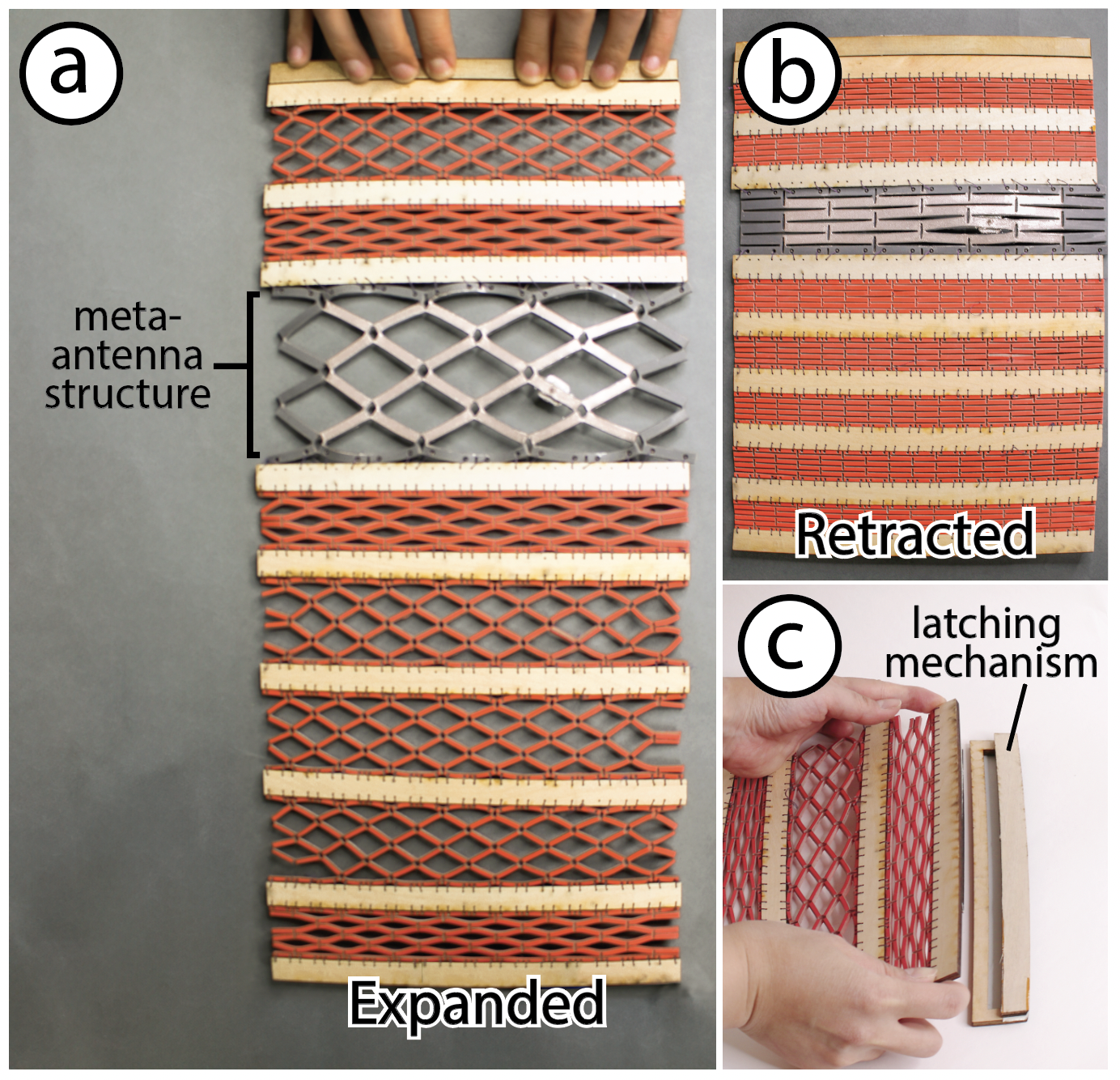
Figure 10: (a) Smart light-adjusting curtain with integrated meta-antenna.(b) Antenna shape and length change as the curtain deforms.(c) Curtain locks in place when expanded using a latching mechanism.
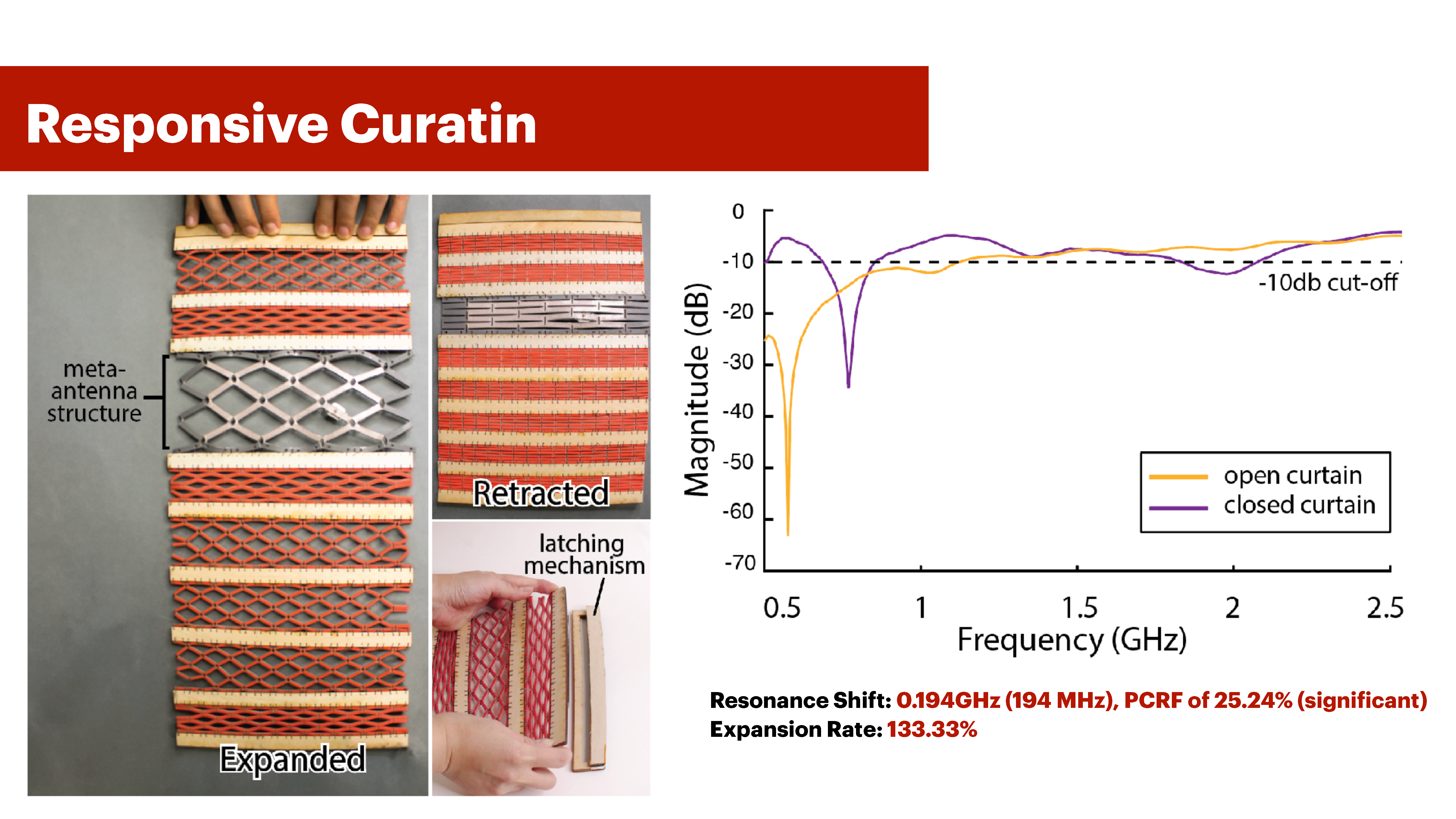
Modern architecture often emphasizes creating dynamic furniture that change shape or morph between states. Even more remarkable is the potential for these state changes to be seamlessly detected, making households more responsive in a smart living environment. One example of an omnipresent and well-understood piece of furniture that undergoes shape change is the curtain. In this application, we demonstrate how Meta-antennas can transform a curtain into a smart piece of furniture that adjusts household lighting based on its expanded (holes) and retracted (no holes) states. By leveraging the inherent kirigami design of our Meta-antenna, which has holes in its expanded state and no holes in its retracted state, we map the expanded state to dim the room lights as it allows natural light to enter. In contrast, the retracted state, with no holes, increases the room brightness. We constructed our metamaterial expandable curtain with a middle segment functioning as a meta-antenna (Figure 10). The main interaction primitive we showcase in this example is expansion/retraction. As shown in Figure 11, when the curtain expands by 133.33%, the resonance frequency shifts by 0.194GHz (194 MHz), which is a PCRF value of 25.24% (significant, Section 3.1). This shift in frequency is detected by our VNA and results in adjusting the LED strip’s brigthness. As illustrated in Figure 11 (a-b), when the curtain is expanded, outside lighting enters the room, thus the LED dims out, and when the curtain is retracted (ie.no outside light enters the room), the LED turns on.
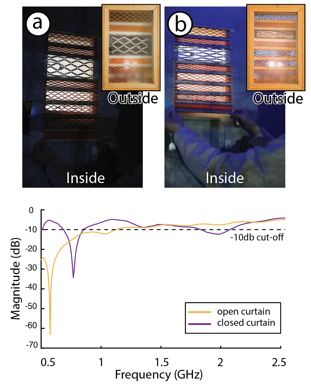
Figure 11: This smart light-adjusting curtain dims as it expands
ADAPTIVE PERSONAL ELECTRONIC DEVICES
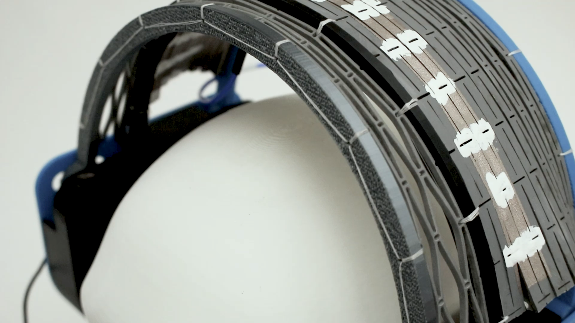
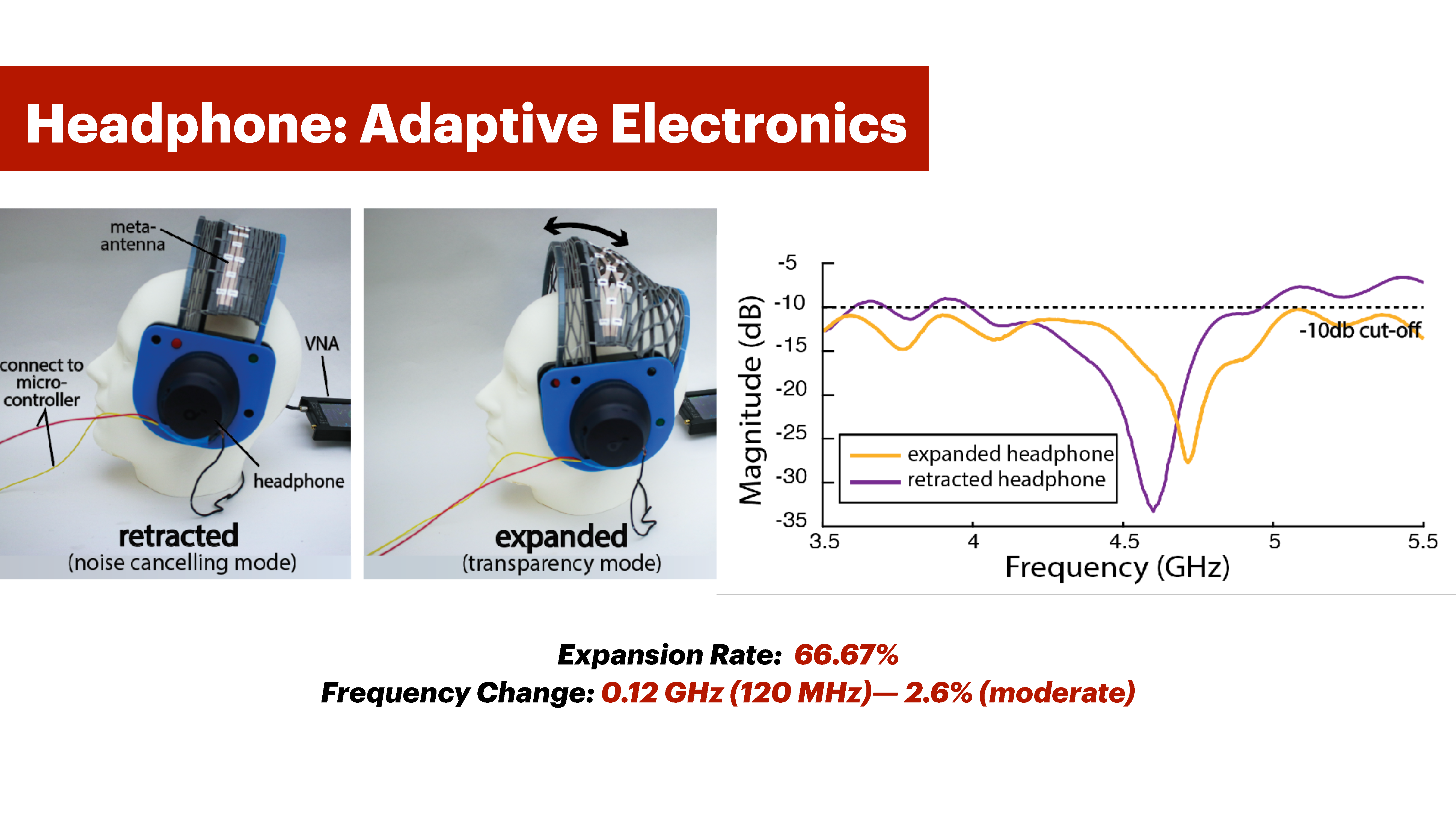
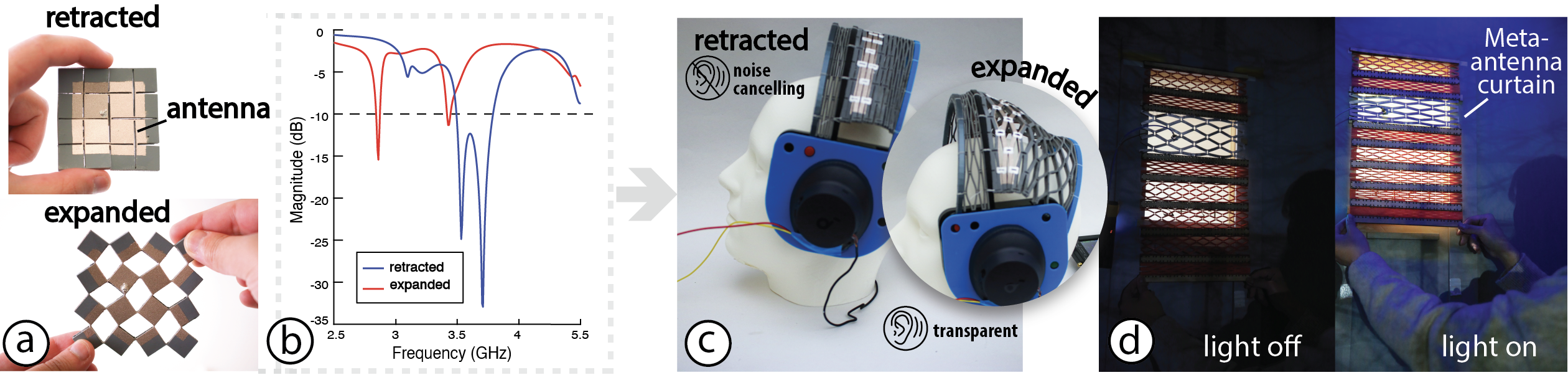
Meta-antennas can also be integrated into adaptive personal electronic devices. We demonstrate this through a smart headphone that seamlessly transitions between noise-canceling and transparent modes, while also providing a clear physical indicator of which mode it is in. To create the smart headphone, we repurpose an existing headphone using an IRFZ44N MOSFET (transistor) to enablemode switching. In our case, the switch between modes occurs when the central component of the headphone shown in Figure 12-a, identified as the Meta-antenna, expands and bends (interaction primitive). This expansion of 66.67% alters the resonance frequency by 0.12 GHz (120 MHz), which is a resonance shift of 2.6% (moderate, Section 3.1). This change adjusts the transistor pin, switching the headphone mode from noise-canceling to transparent
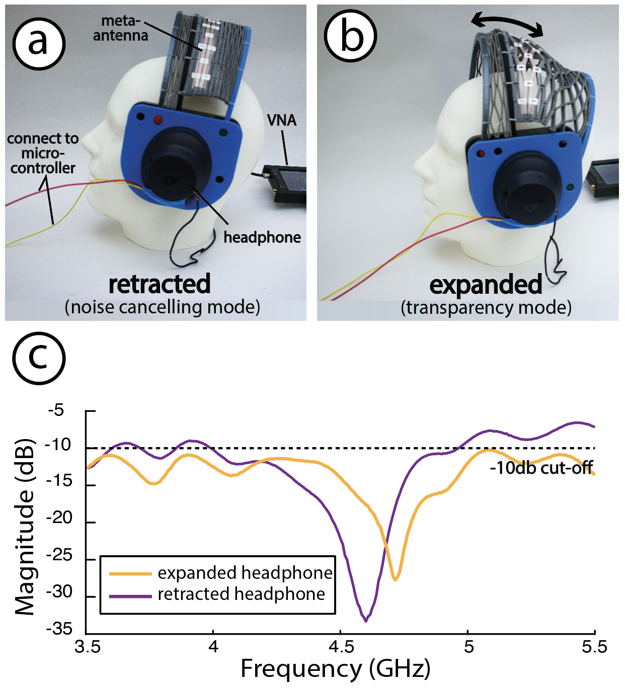
Figure 12: This shape-adaptive noise-control headphone changes from noise canceling mode to transparency mode upon expanding.
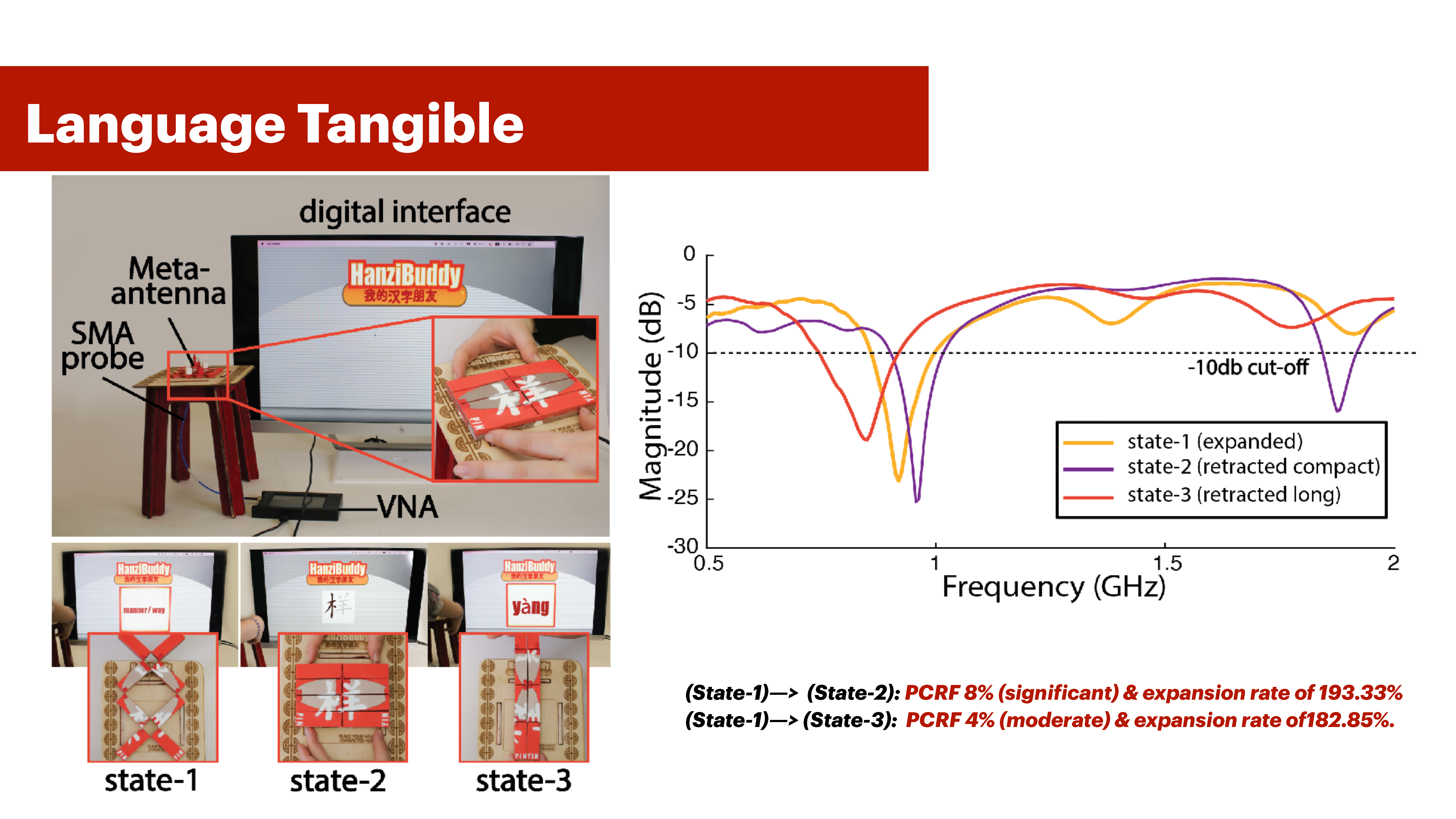
INTERACTIVE TANGIBLE USER INTERFACES
We leverage the three distinct states generated by Meta-antenna’s rotational deformation (Section 4) to encode meaningful interactions within each of its physical configuration. In this application, we demonstrate a language learning tangible that is used as a “dynamic” flashcard for learning Chinese characters (Hanzi) and interacts with a digital interface. When learning Hanzi characters, Chinese learners memorize three sets of information: the reading of the character (Pinyin), its writing, and its meaning. This three-piece information application is well-suited for Meta-antennas, which operate in up to three distinct states. To illustrate this, we embedded the information retaining the Hanzi character’s meaning into State-1, its writing into State-2, and its reading (Pinyin) into State-3. We then built a Processing UI that interfaces with the Meta-antenna Hanzi as seen in Figure 13. The UI shows the character meaning (State-1), the character stroke order (State-2), and the character’s reading (State-3). As Figure 13-e) shows, the PCRF between States (1-2) is 8% (significant) for an expansion rate of 193.33%, and the PCRF for States (1-3) is 4% (moderate) for an expansion rate of 182.85%. The antenna is patterned with an oval patch shape that changes pattern across states as seen in Figure 13 (b-d).

Figure 9. This fishing rod can sense its own angular position, rotational velocity, and number of rotations and can be used as a controller for gaming and VR experiences.
TECHNICAL EVALUATION
We conducted a technical evaluation to assess how close the results are between our Meta-antenna design tool’s simulation predictions and ground truth data for four meta-antenna structures. Addition ally, we compared our fabrication method against three other fabrication approaches, including multi-material 3D printing, across five categories in fabrication and signal quality. Finally, we evaluated the electrical durability of our hinges under reverse cyclic loading, cyclic compression, and bending, as well as the impact of flexible acrylic-paint coating on Meta-antenna’s resonance frequency.
ANTENNA FREQUENCY RESPONSE MEASUREMENT SET-UP
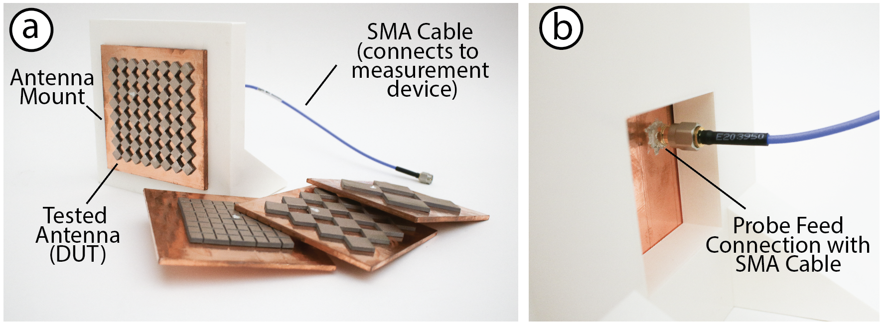
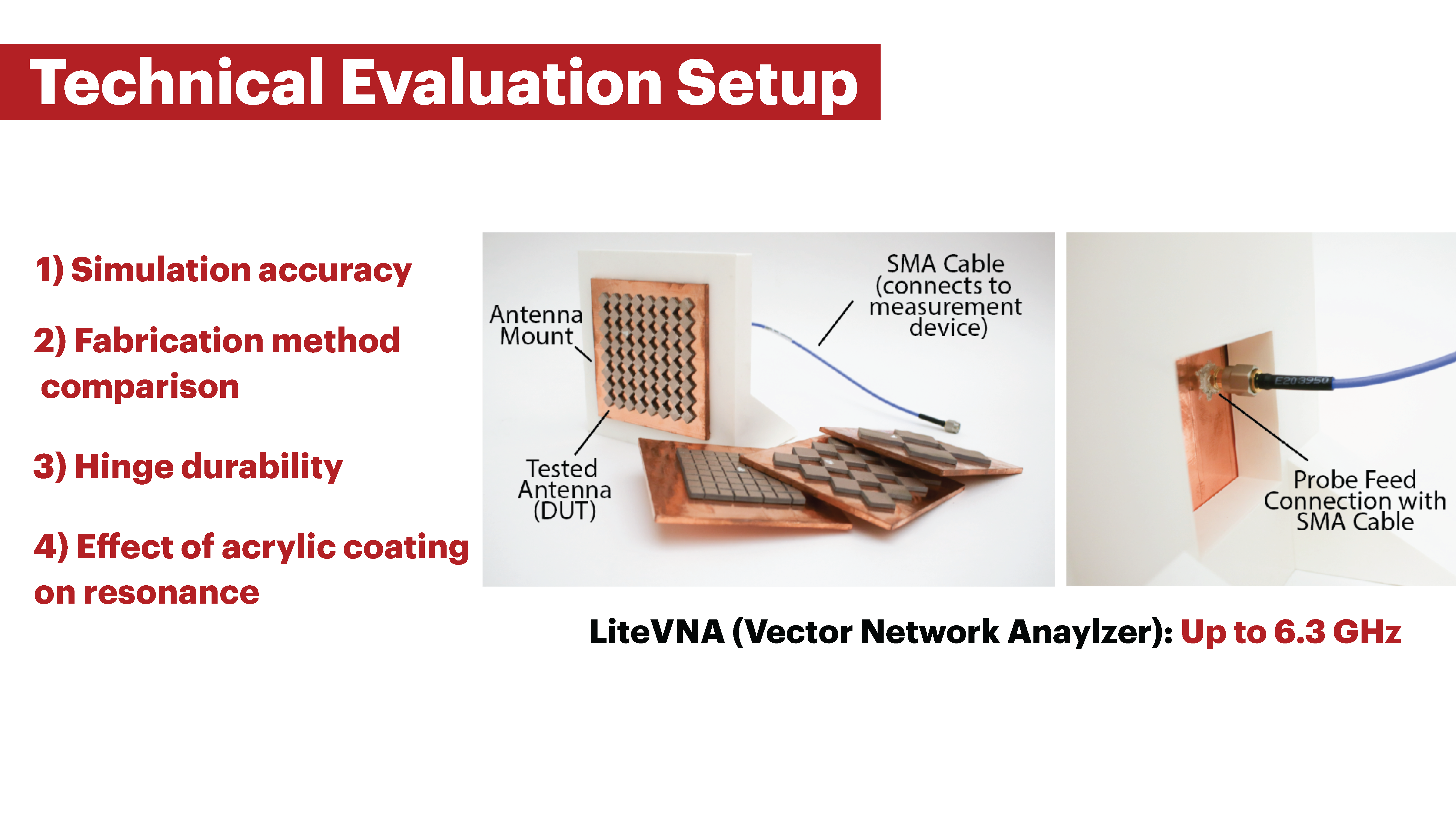
Figure 14: (a) Experimental setup showing the tested Meta-antennas mounted on a 3D-printed antenna holder and connected to an SMA cable for measurement. (b) Close-up of the probe feed connector between the Meta-antenna and SMA cable.
Physical Testing Setup: Our experimental setup consists of a 3D printed mounting jig to attach the DUT (Device Under Test) antenna structures onto (Figure 14). The jig has a hole which allows for routing the SMA cable from the DUT to the VNA, ensuring that the SMA cable is straight. For frequency response testing, we use a LiteVNA (Vector Network Analyzer), which has a frequency range up to 6.3GHz.
Simulation Testing Tool: We use ANSYS HFSS for our simulations. We run a return loss study through our Meta-antenna editor (Section 5) for frequencies from 500 MHz to 6.3 GHz. We use the default values of electrical and magnetic properties for our dielectric substrate from the ANSYS system library under “rubber hard”. The output of the study is a graph of frequency as a function of return loss magnitude (dB).
ACCURACY BETWEEN SIMULATION AND FABRICATED RESULTS
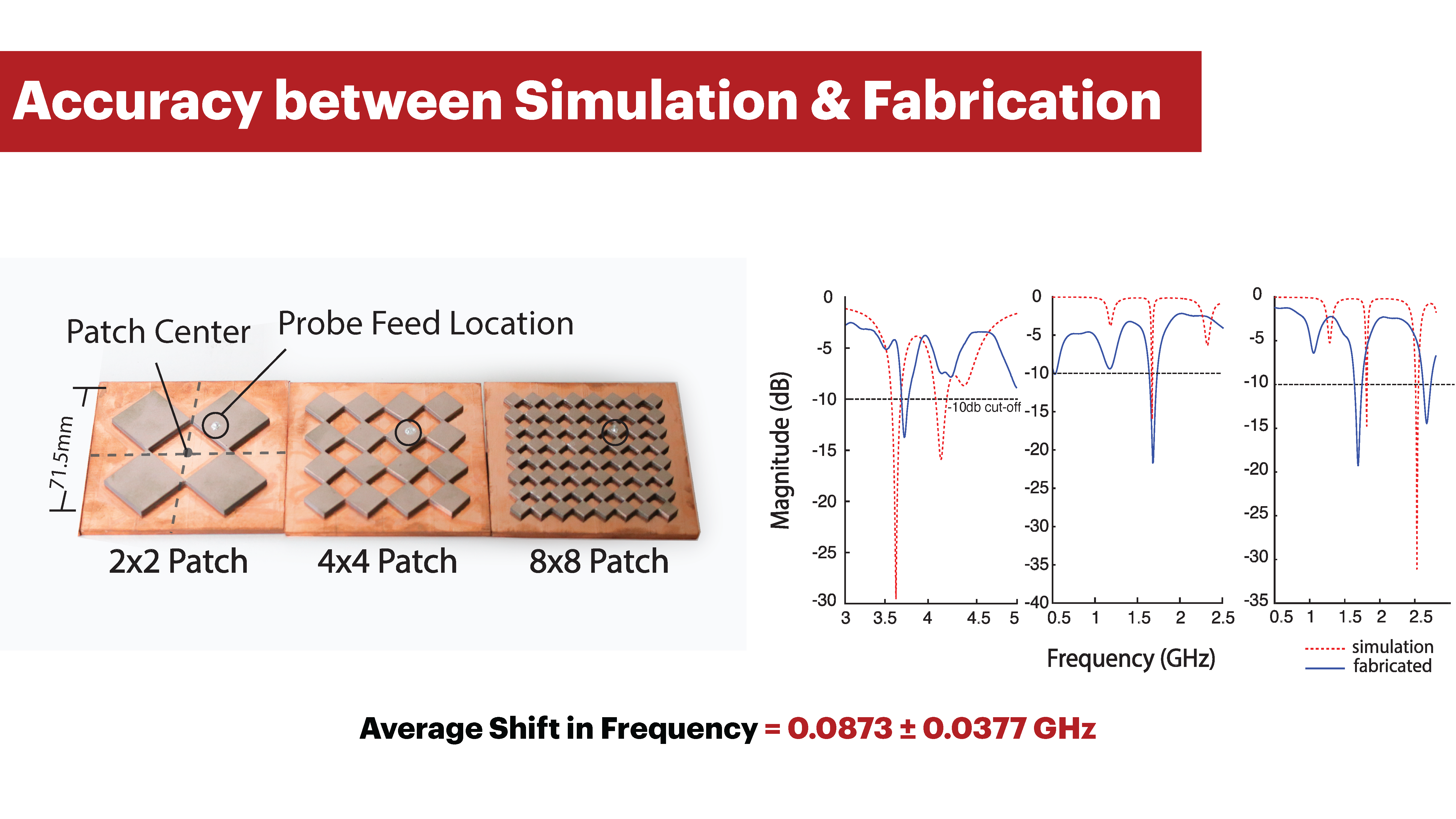
We compare the results from our Ansys simulation tool to the fabricated results across three different structures to evaluate our simulation’s accuracy
Apparatus:
We used the apparatus in Section 8.1 to measure the return loss of the fabricated samples. We constructed three structureswith Meta-antenna densities of 2x2, 4x4 and 8x8, all with a size of 71.5cm x 71.5cm- a size expected to resonate within our VNA range. Our constructed the Meta-antennas all have static solid grounds from copper tape. The static ground is to eliminate any potential mechanical deformation while collecting data for comparison. All antennas have the same SMA probe location.
Procedure: We collect our frequency response data through the VNA in two ranges: the first from 500 MHz to 3 GHz, and the second from 3GHz to 5.3 GHz, each calibrated for that range and each with 410 data points. As for the simulation, we use the setup generated by our editor (Section 5).
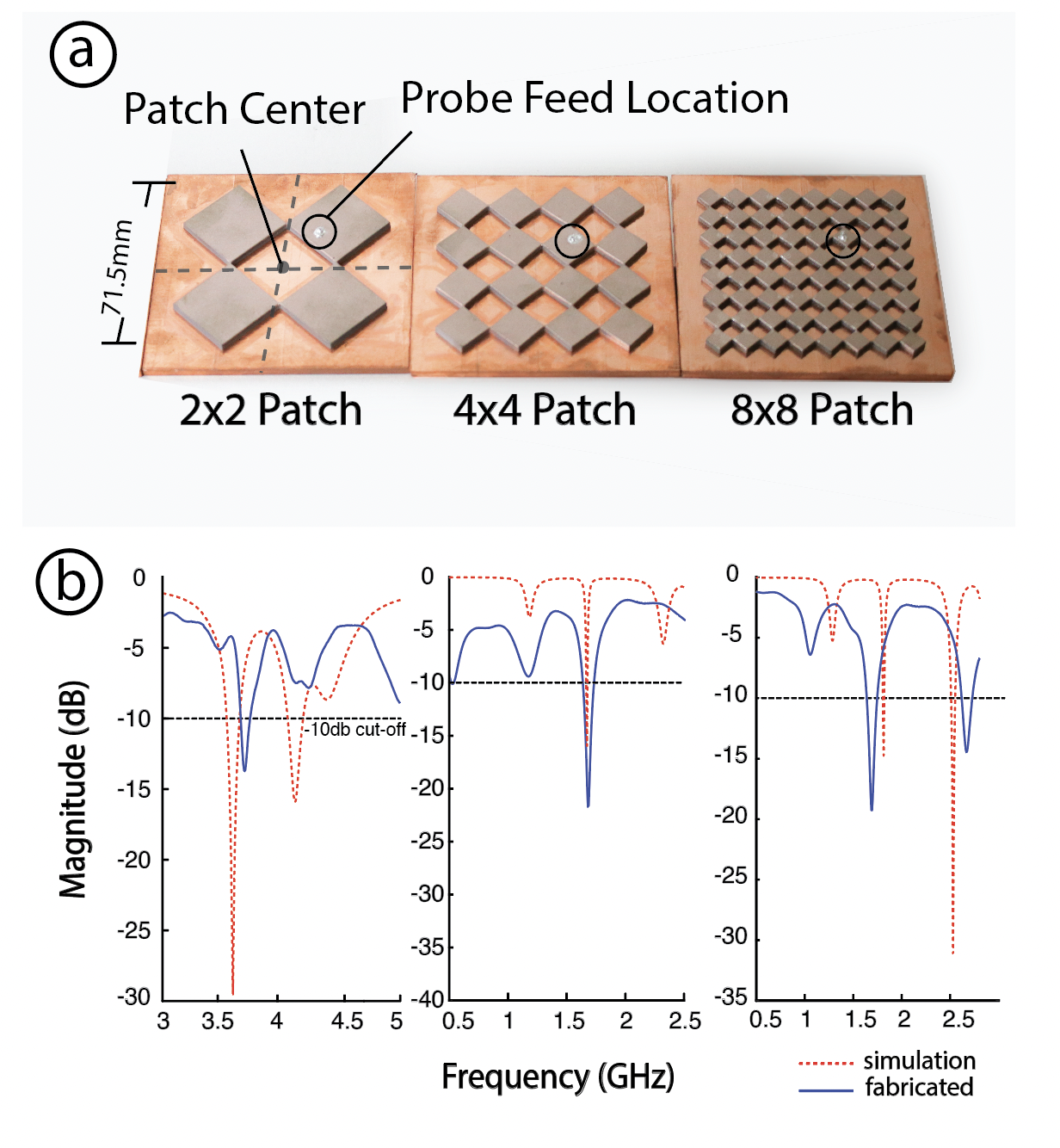
Figure 15: Comparison between simulated and fabricated Meta-antenna structures.
Results :
We report the measured and simulated resonance frequency values (return loss) in Figure 15. As can be seen in the figure, there are some noticeable differences between the values. We report an average shift of 0.0873 GHz (𝜎 = 0.0377𝐺𝐻𝑧). These differences are due largely to differences in matching conditions, especially the dielectric value and loss tangent of the rubber which change based on frequency. In our lab, we could only measure the dielectric constant up to 300 kHz, which was insufficient for the simulation. As a result, we opted to use the default values from the Ansys library, since measuring the dielectric constant at frequencies higher than 300 kHz requires specialized optical equipment.
FABRICATION METHODS COMPARISON
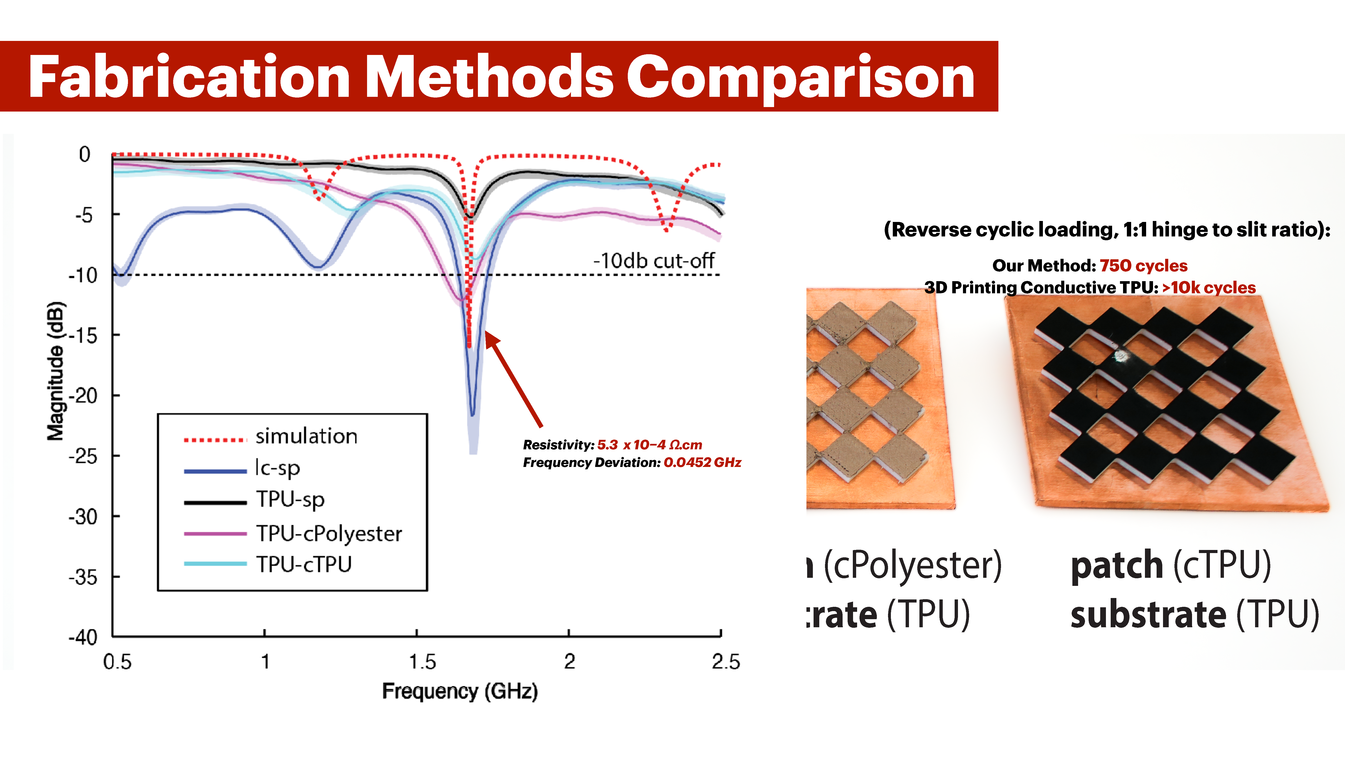
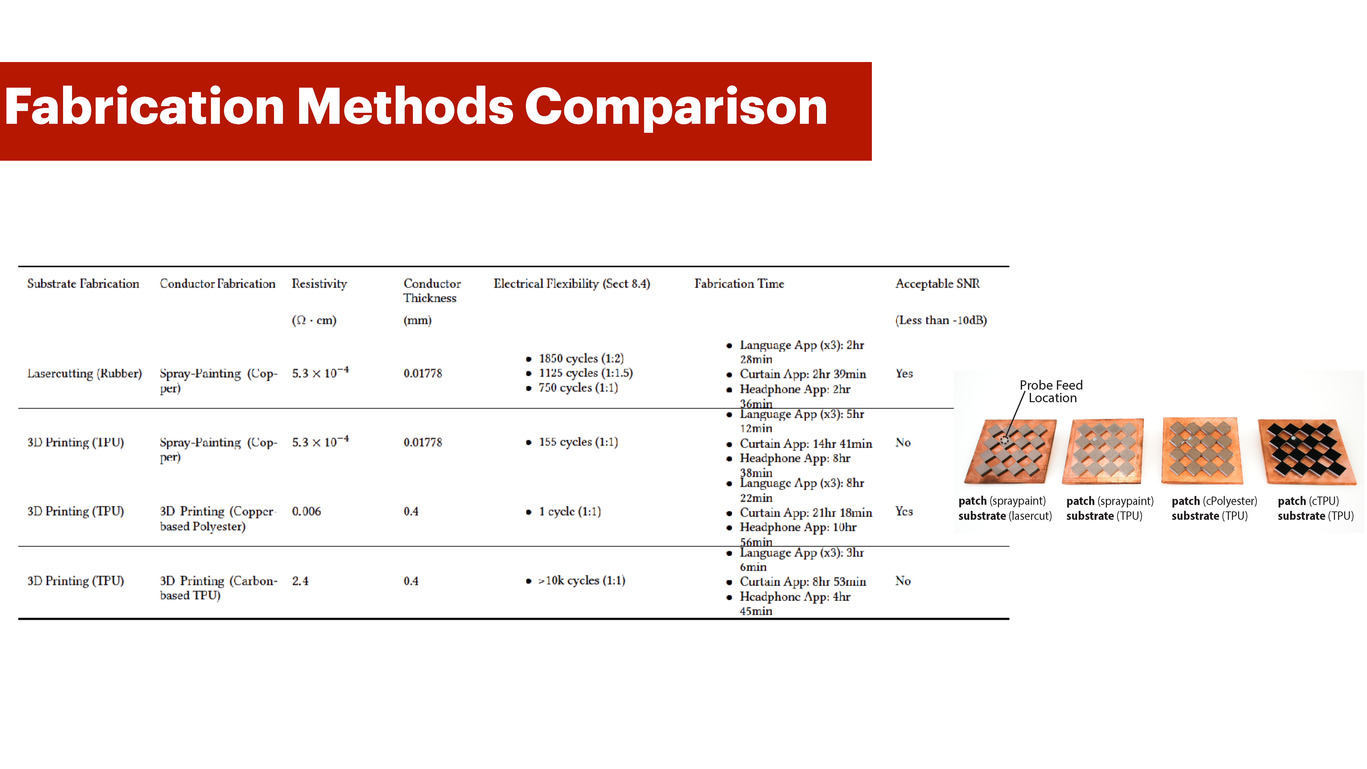
Next, we compare our fabrication method of lasercutting then spray painting against three alternative approaches across five evaluation criteria as illustrated in Table 1.
| Substrate Fabrication | Conductor Fabrication | Resistivity (Ω·cm) | Conductor Thickness (mm) | Electrical Flexibility | Fabrication Time | Acceptable SNR (Less than -10dB) |
|---|---|---|---|---|---|---|
| Lasercutting (Rubber) | Spray-Painting (Copper) | 5.3 × 10⁻⁴ | 0.01778 |
|
|
Yes |
| 3D Printing (TPU) | Spray-Painting (Copper) | 5.3 × 10⁻⁴ | 0.01778 |
|
|
No |
| 3D Printing (TPU) | 3D Printing (Copper-based Polyester) | 0.006 | 0.4 |
|
|
Yes |
| 3D Printing (TPU) | 3D Printing (Carbon-based TPU) | 2.4 | 0.4 |
|
|
No |
Sample Preparation: We prepared 4 samples of the same Meta-antenna structure we used in Section 8.2. The only difference is that we fabricate three of those samples using 3D printing. The first sample (lc-sp) is lasercut then spray-painted using our default fabrication method. The second sample (TPU-sp) is 3D printed with TPU on an Ultimaker S5, then spray-painted with our copper-based spray paint. The third sample (TPU-cPolyester) is multi-material 3D printed on an Ultimaker S5 with TPU and Electrifi Filament from Multi3D (copper-based polyester) which is currently the most conductive filament in the market. The fourth sample (TPU-cTPU) is 3D printed in TPU and carbon-based TPU (Reprapper). Because the carbon-based TPU filament is only available in 1.75mm diamater, it is not compatible with Ultimaker 3D printers. As a result, for this sample, we used a Prusa XL for multi-material 3D printing. While all structures are identical in thickness and geometry, the TPU filament is stiffer than the rubber sheets in our default fabrication method. TPU has 95A shore hardness, while the rubber sheets are at 60A. This means that TPU is more resistant to deformation.
Procedure: For VNA resonant frequency testing, we followed the same procedure as in Section 8.2. Figure 16 shows the results.
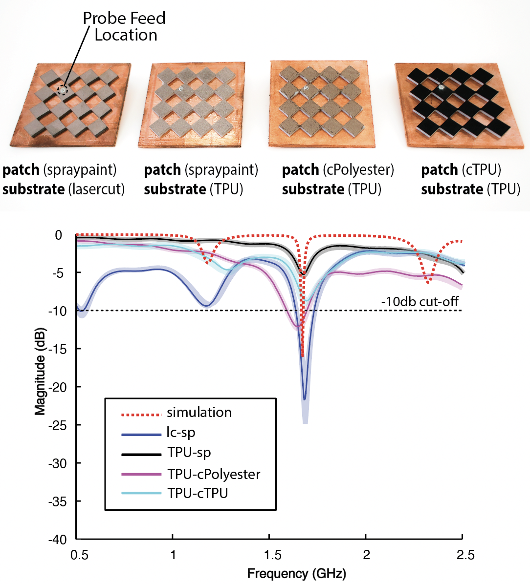
Figure 16: Difference in frequency response across four different fabrication methods of a Meta-antenna geometry.
Results: From both Table 1 and the frequency response results in Figure 16, we see that laser cutting and spray-painting is the most effective fabrication method for four categories out of five. Our choice of conductor has the lowest resistivity (5.3 × 10⁻⁴ Ω · cm) making it a superior choice as a Perfect Electric Conductor (PEC) in comparison. Our fabrication method offers the shortest fabrication time for scaled-up applications (curtain: 2 hours 39 minutes), uses the smallest conductor thickness (0.01778 mm), and provides an acceptable signal-to-noise ratio (SNR), with only a 0.0452 GHz deviation from the resonant frequency in the simulation data. The only metric where our method is not as strong is the number of reverse cyclic compressions, which we discuss Section 8.4. The Carbon-based TPU remains electrically stable after 10,000 reverse compressions for a 1:1 slit-to-hinge ratio, while our method lasts 750 cycles for the same ratio.
ELECTRICAL CONNECTIVITY ENDURANCE OF META-ANTENNA UPON CYCLIC COMPRESSION
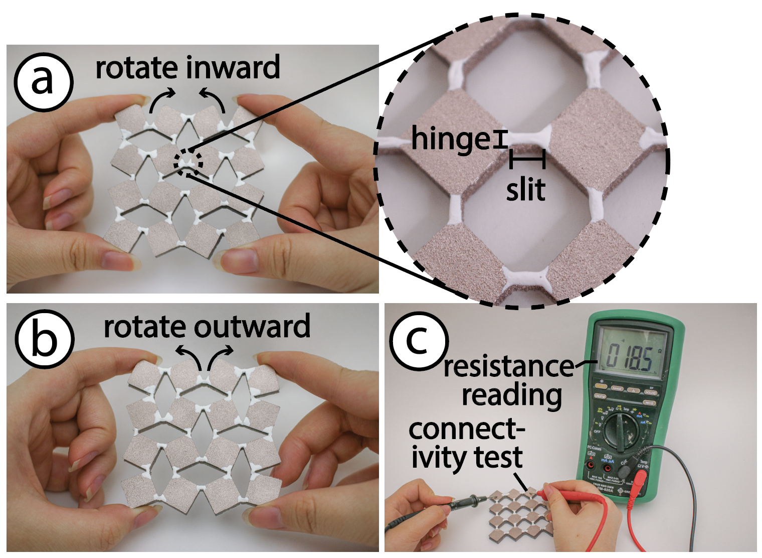
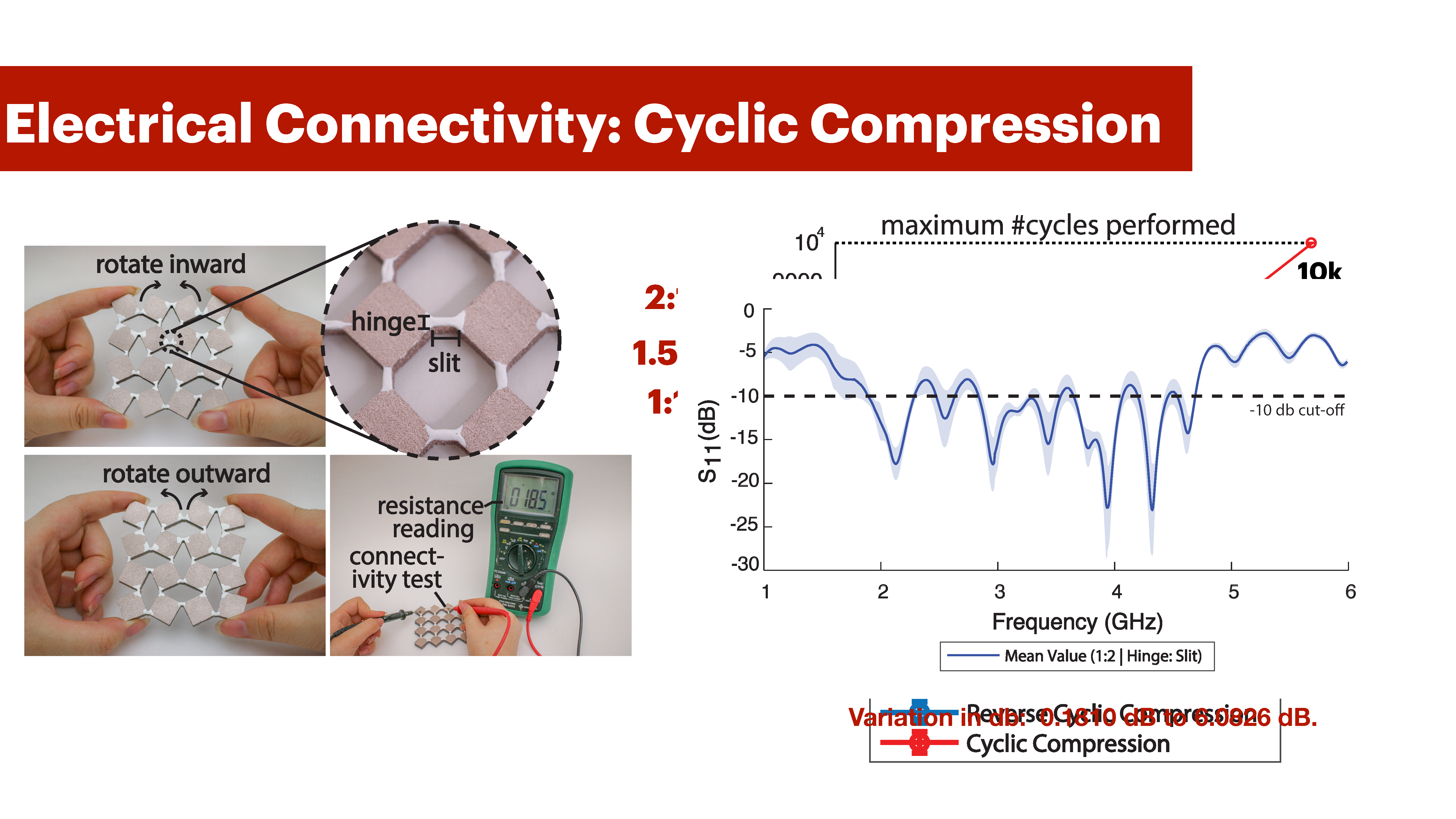
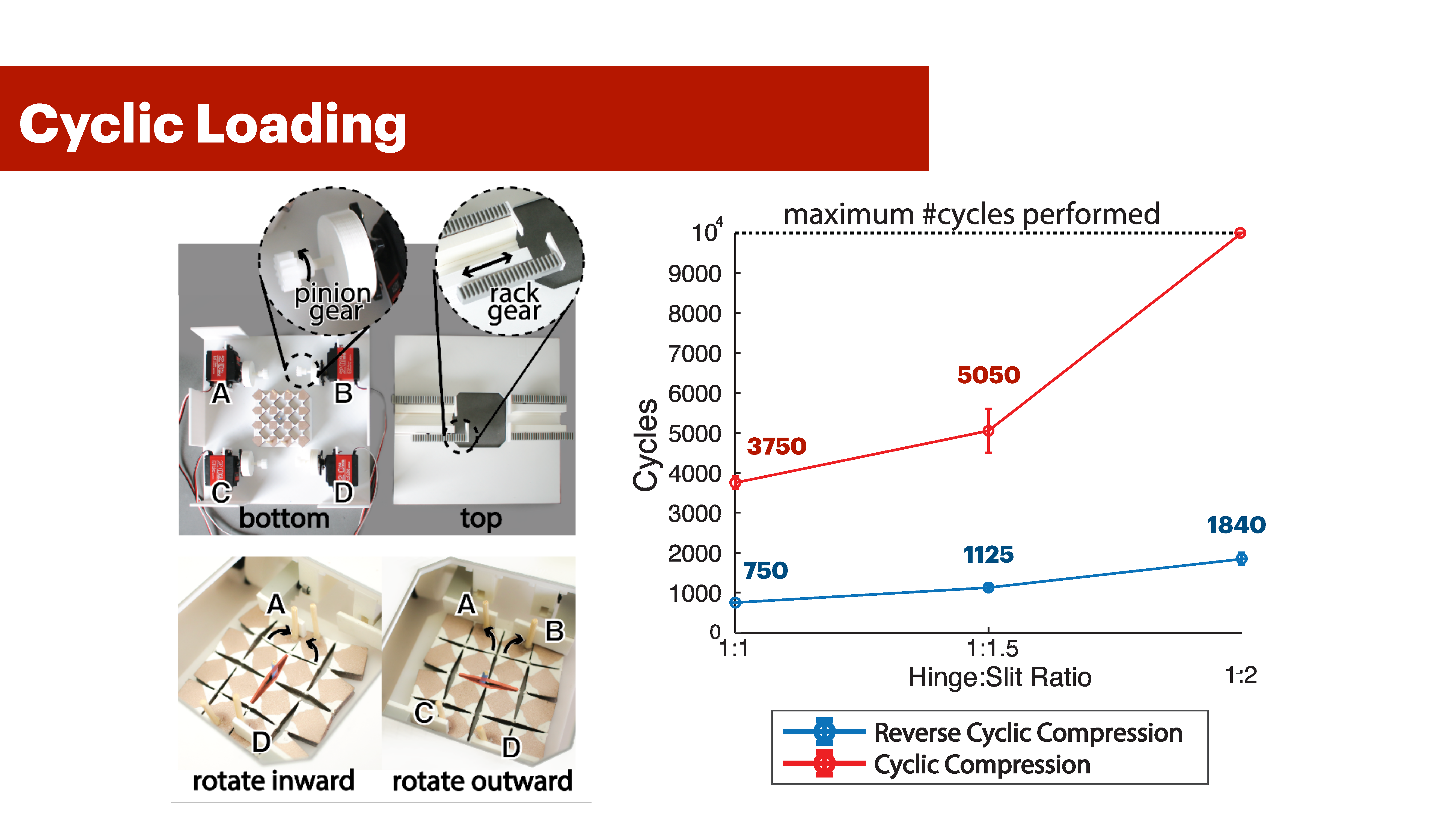
Figure 17: Reverse cyclic rotation consists of (a) inward rotation of the unit cells and (b) Outward rotation of the unit cell. The inset highlights the hinge and slit features of a Meta-antenna geometry. (c) We test for electrical connectivity upon cyclically compressing using a multimeter.
Apparatus: Our apparatus consists of a compressing mechanism, a multimeter and 3 structures with a hinge:slit ratio equivalent to 2:1, 1.5:1 and 1:1 and L:W ratio (r) of 1:1. Each designed structure was fabricated and tested 3 times. The thickness of the rubber we chose for this evaluation is 5.4mm. In all structures, the hinge width is fixed to 1.5 mm, whereas the slit is varied according to the previous ratios. The 1.5mm hinge size is the minimum required to ensure sufficient surface area for the conductive material to adhere to, while also maintaining the mechanical stability of the structure to prevent breakage. Our compressing mechanism consists of four actuators that attach to the specimen at four points. Our actuators are programmed to move forward and backward through a rack-pinion mechanism. When all four actuators move forward-backward cyclically, the Meta-antenna goes back and forth between States 1 and 2 (Section 4). we refer to this deformation as cyclic compression. When actuators A and D push forward, the structure compresses to state 2, and when B and C are actuated in a pair, the structure compresses to State-3. We refer to this deformation as reverse cyclic loading since the structure rotates inwards then outwards (Fig. 17).
Procedure: We performed two sets of evaluations on our fabricated metamaterial antenna, consisting of 3 samples per design across 3 designs (18 test total). The first evaluation was the reversed cyclic compression test, and the second the cyclic compression test. In the first test, we rotate each structure, i.e. compress it, clockwise (actuators A and D)- then counter-clockwise (actuators B and C) interchangeably. One cycle corresponds to a motion from the expanded state to a retracted state and then back to the expanded state. After each cycle from 1-10, we check for connectivity using a multimeter for all unit cells, then check every 5 rotations up to 100, then every 10 up to 200, 50 up to 1000, and 100 after 5000. We repeat this for all samples. In the second test, we follow the same procedure but the actuators move forward and backward to compress and uncompress the structure.
Results: Figure 18 shows the results of our experiment. We conclude that as the hinge:slit ratio increases, the Meta-antenna compresses for more cycles while still being electrically connected. For example, a 1:2 ratio undergoes an average of 1850 reversed compression cycles, and more than 10k compression cycles in applications like the curtain and headphone designs.On the hand, 1:1.5 and 1:1 ratios have reverse compression and compression cycles averages of (1125, 5050) and (750, 3750) respectively. This is above the commonly accepted high-cycle fatigue test value of at least 10k [16].In addition, Figure 18-d shows how much the signal varies upon 5000 cyclic compressions from 1-6 GHz for the 1:2 hinge to slit ratio samples. The maximum standard deviation per frequency was 6.0826 db, and the minimum was 0.1810 db.
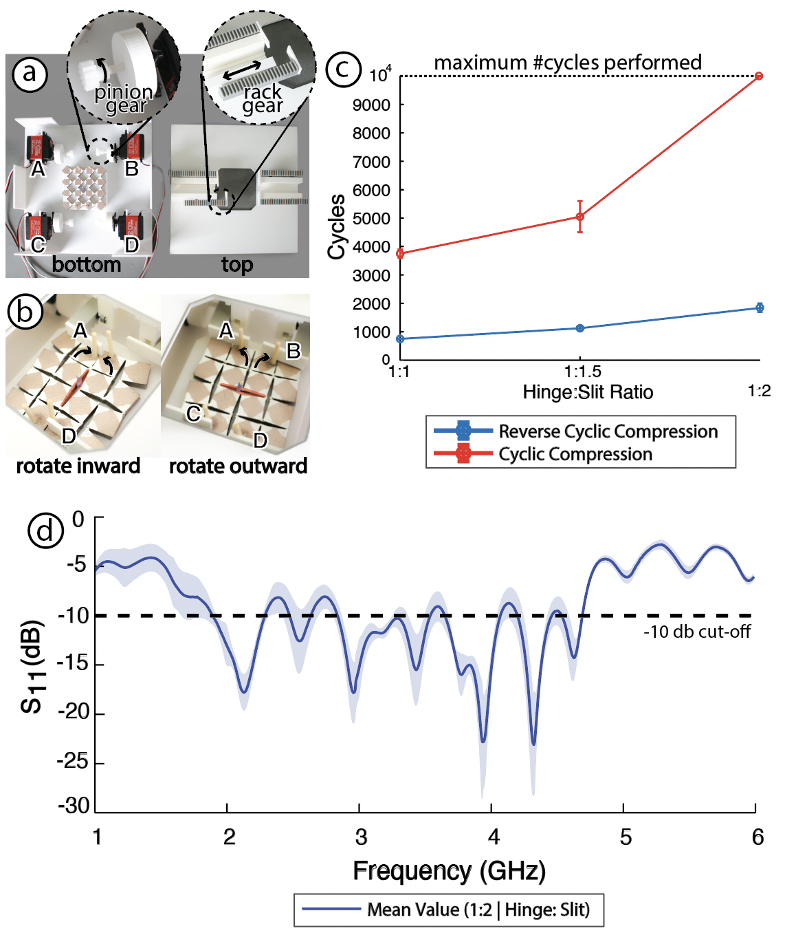
Figure 18: (a-b) Experimental set-up used to cyclically compress Meta-antenna square geometries using a rack-pinion mechanism. (c) Square antennas can compress beyond 10k cycles, and up to 2k reservable cycles. (d) The antenna frequency signal for 1:2 hinge to slit ratio samples remains statistically consistent even after 5000 compression cycles.
ELECTRICAL CONNECTIVITY ENDURANCE OF META-ANTENNA UPON BENDING
In Section 3, we discuss how Meta-antennas can be bent, which we demonstrate through our headphone application (12). In this section, we conduct a technical evaluation to show the bend radii extent of our Meta-antennas and how they are influenced by Meta- antenna pattern density.
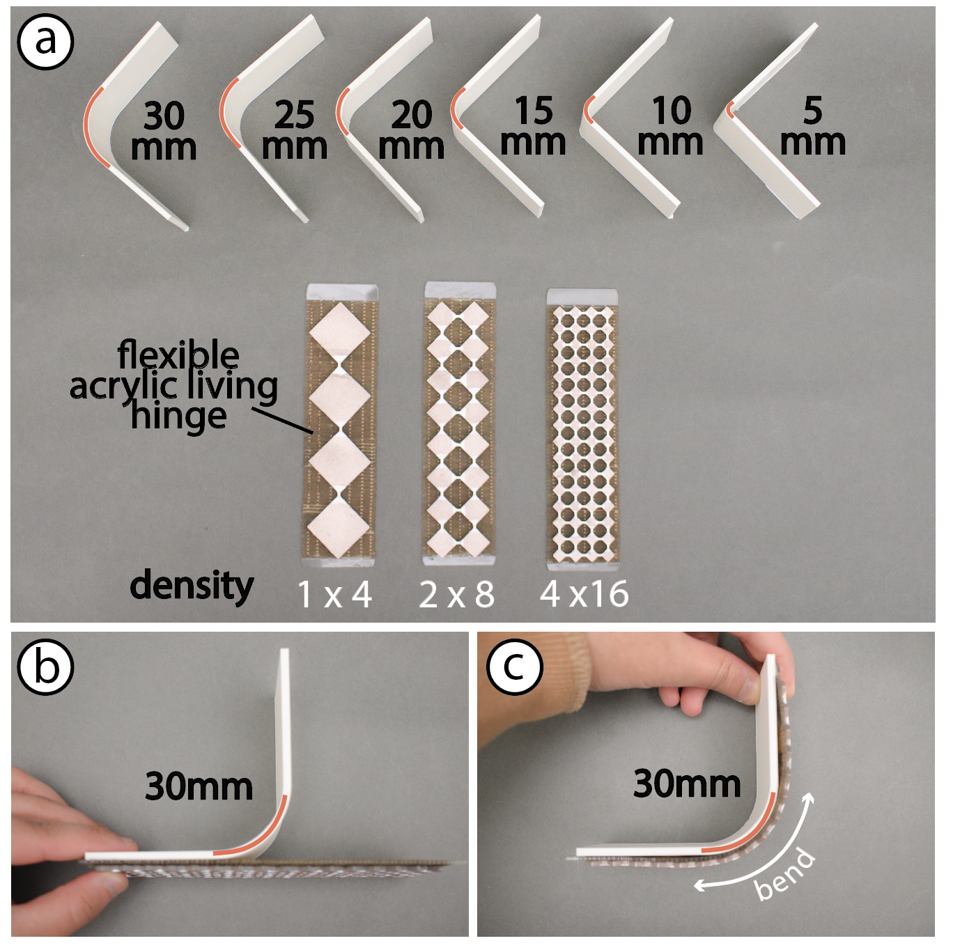
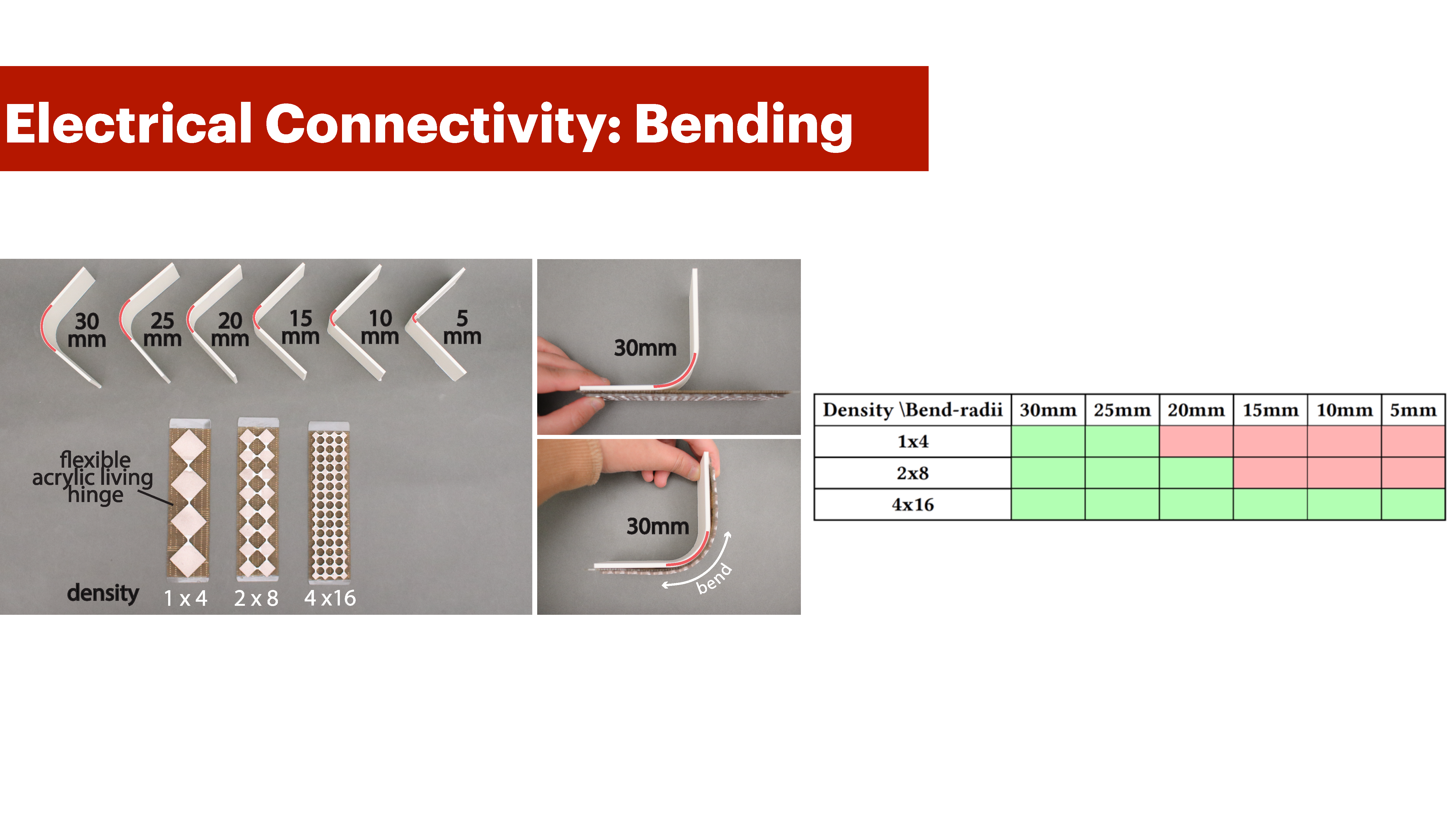
Figure 19: Experimental setup for bending evaluation. (a) Fabricated bend radii templates from 30mm to 5mm with Meta-antenna densities (1×4, 2×8, 4×16).(b-c) Side view of Meta-antenna bent around 30mm bend template.
Apparatus: We 3D printed 6 bend radii templates that increment by 5mm from 5mm to 30mm (Figure 19-a). We use these templates to bend our structures. We lasercut a Meta-antenna structure of 15 cm x 4 cm with three different unit cell densities (1x4), (2x8) and (4x16), (x3 samples each). The thickness of the rubber is 2.3mm and the size of the hinge is constant across all three. We then attached each structure to a lasercut living hinge with slit separation size of 1mm. The living hinge structure is designed to curve to a 5mm bend radius without breaking. We attach the structures to the living hinge to ensure that as we bend, we are not introducing any additional co-axial stretching as we are interested in evaluating pure bending.
Procedure: As seen in Figure 19-b and c, we roll each Meta-antenna structure around the radii templates starting from 30mm bend radii to 5mm. During and after each bend operation we check for electrical connectivity between all unit cells using a multimeter.
| Density \ Bend-radii | 30 mm | 25 mm | 20 mm | 15 mm | 10 mm | 5 mm |
|---|---|---|---|---|---|---|
| 1×4 | ||||||
| 2×8 | ||||||
| 4×16 |
Results: As table 2 shows, Meta-antennas can still be electrically connected while bent to 5mm bend radii (4x16 density pattern). We also conclude that increasing pattern density makes the structure more flexible. In comparison to the 4x16 pattern, the 2x8 and 1x4 patterns electrically break at 15mm and 20mm bend radii respectively. In general, higher unit cell densities introduce more holes in the structure, which make the material less rigid for bending
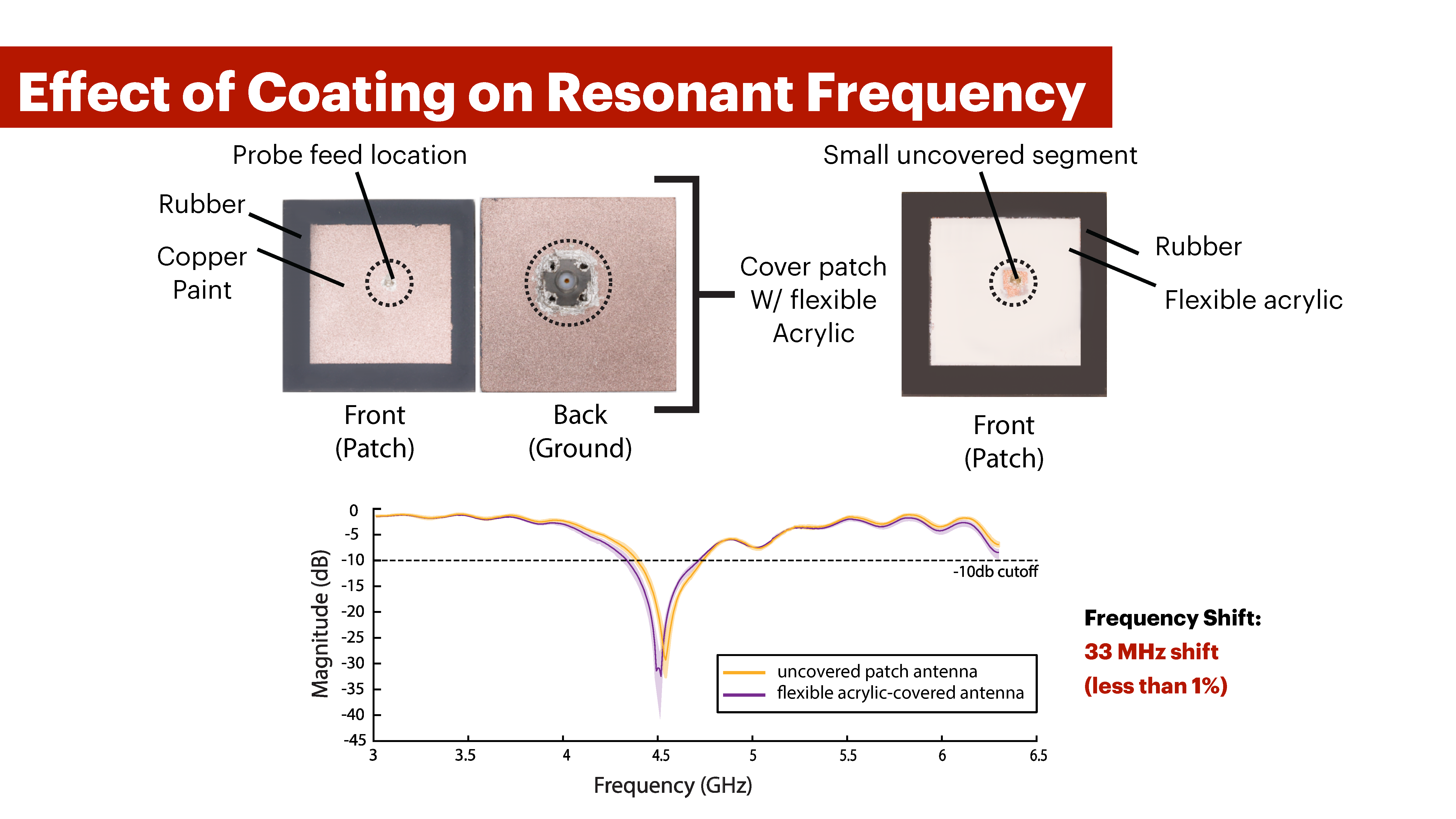
EFFECT OF COATING ON RESONANT FREQUENCY
Next, we evaluate the effect of coating our Meta-antenna with the flexible acrylic on its resonant frequency. The flexible acrylic is what we use to cover the Meta-antenna hinges to make them electrically flexible as described in Section 6.3.
Apparatus: We use the same test-set up in Section 8.1. We fabricated a square patch with dimensions 53mm x 53mm and measured the sample at three setup intervals. To ensure we don’t report changes due to inconsistencies in fabrication, we did not fabricate new samples. Instead, we covered the conductive patch region of the original sample with flexible acrylic and measured it again at three different intervals. Additionally, we laser-cut a mask to main- tain access to a small area around the probe for checking SMA connectivity, as shown in Figure 20.
Procedure: We used the same procedure as Section 8.2.
Results: Figure 20-b highlights the resonant frequency for our covered and uncovered patches. In general, the difference in the resonance frequency between the average recorded values for the non-coated structure and flexible acrylic-covered structure is 0.033 GHz (33 MHz). This corresponds to 0.731% PCRF, which according to our criteria in Section 3.1 is less than 1%, and hence, insignificant for mechanical deformation
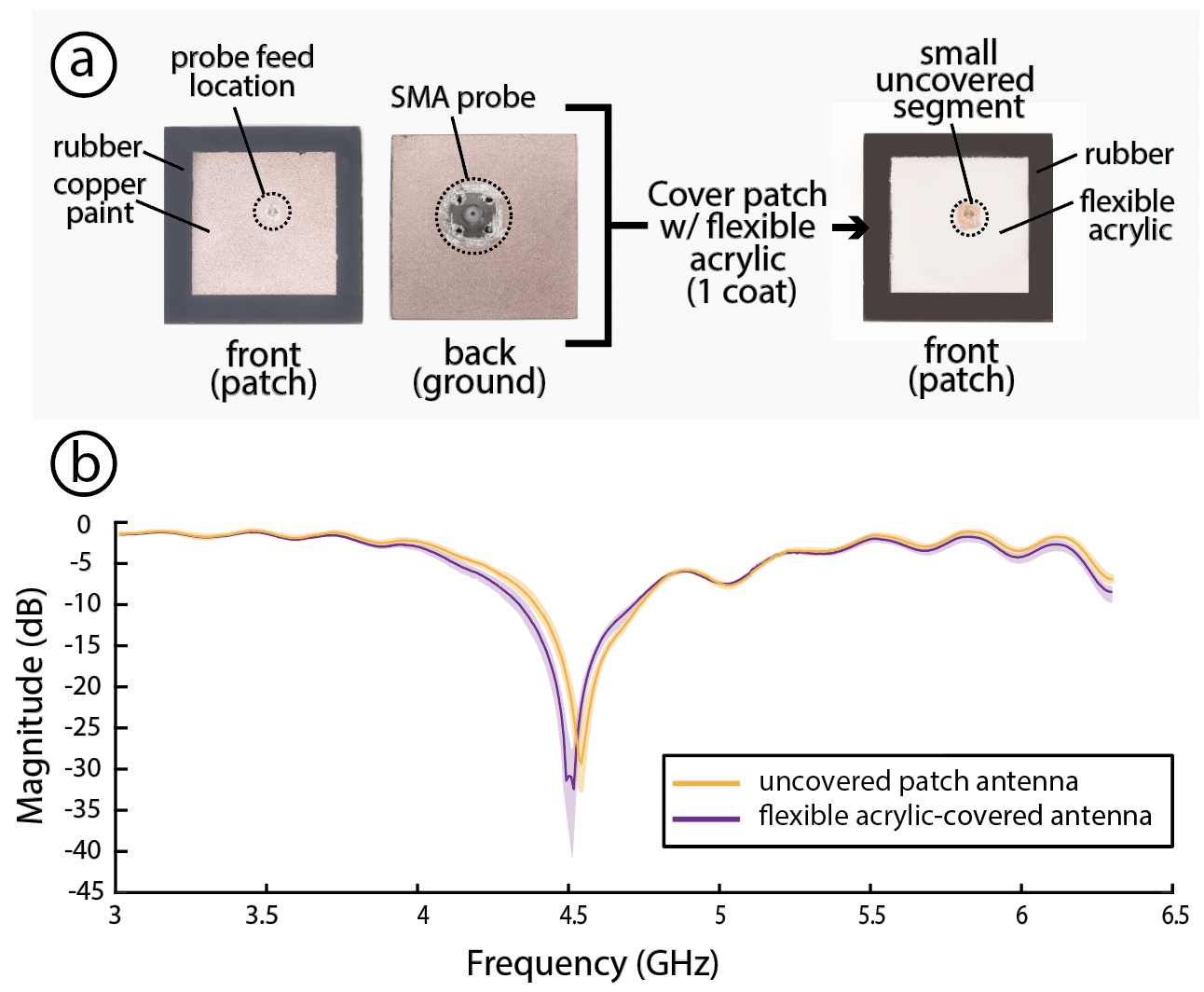
Figure 20: Covering Meta-antenna structure patches with flexible acrylic results in minimal shift in its resonant frequency.
DISCUSSION AND FUTURE WORK
In this section, we discuss the limitations of Meta-antenna and potential directions for future research.
Exporting the Meta-antenna Structures:
Our current Meta-antenna design tool in Ansys does not support direct export of faces or patterns into DXF files. As a result, users must first open the .obj file in a CAD program, and manually project the faces of the Meta-antenna to generate DXF files for lasercutting.
Simulation Support for Bending:
We demonstrate how Meta-antennas can be used for bending; however, our tool currently does not support bending simulation. That said, users can still gain insights into the expected range of resonance frequencies through the simulation results of the same unbent structure.
Cyclic Loading:
We demonstrated the electrical durability of the Meta-antenna under cyclic loading for a structure with square (1:1 ratio of L:W) unit cells. We consider the square unit cell to represent a lower bound for our Meta-antenna performance. Increasing the length-to-width ratio beyond 1:1, while still adhering to our mechanical constraints (Appendix A) will make the structure bend more easily, leading to more cycles before failure.
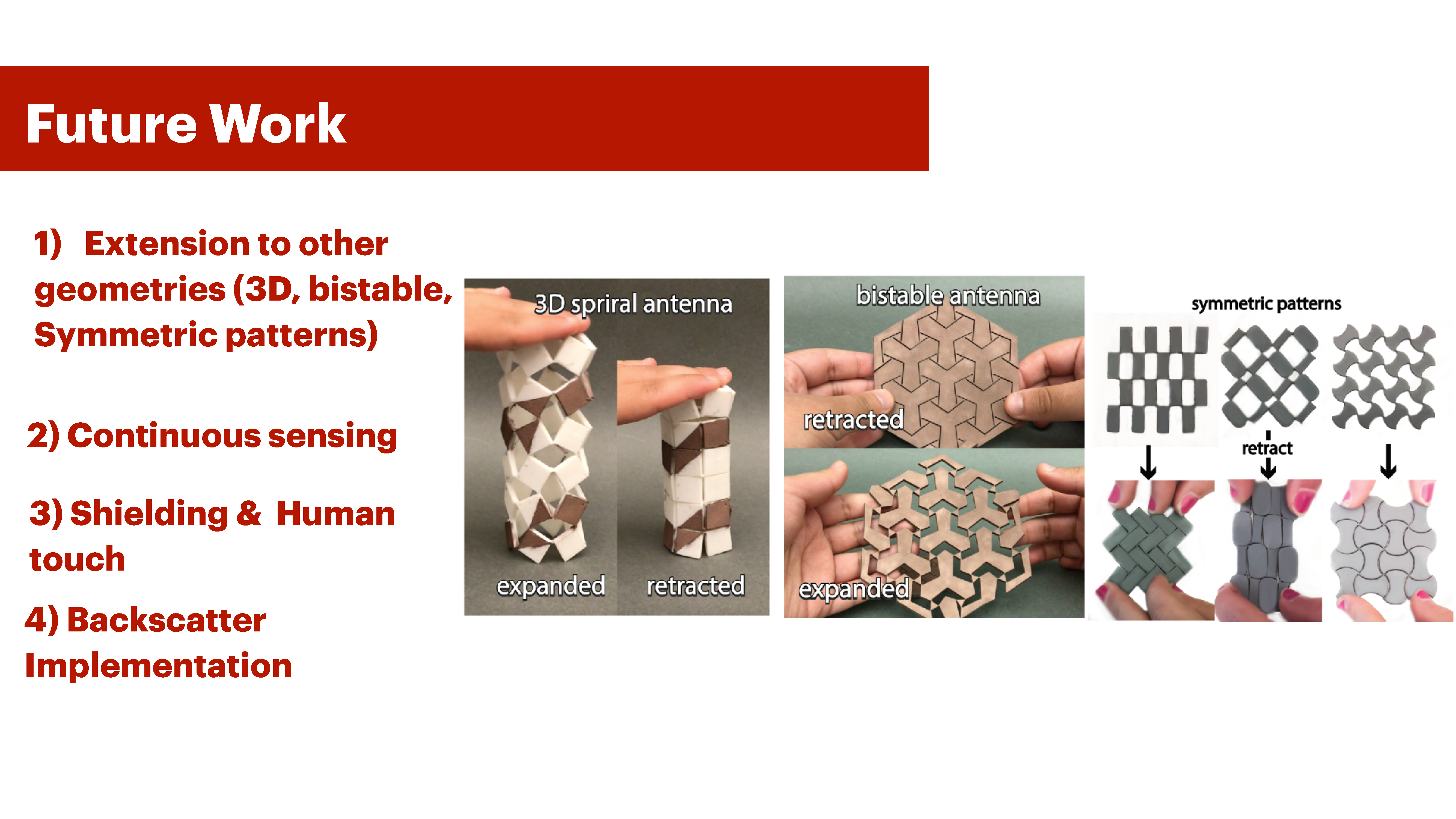
3D deployment:
Our current Meta-antenna implementation generates planar structures that compress/expand, rotate, and bend. In future implementations, we would like to further construct 3D structures that change size radially and axially. We have preliminarily demonstrated this by fabricating a 3D-printed auxetic cylinder structure that is printed in one pass using TPU, then spray-painted with conductive copper paint (Figure 21-a).
Bistable Structures:
In this paper, we fabricated Meta-antennas as monostable structures capable of deforming into three distinct states. However, in the future, we would like our Meta-antennas to also be bistable structures that can retain their configurations without requiring a force to sustain them in place. We demonstrated this by constructing a bistable antenna that expands and retracts radially (Figure 21-b).
Extending Meta-antenna to Other Symmetric Patterns:
In this project, we demonstrated Meta-antenna's working principle for rotating grid structures that are rectangular. However, our design space supports other wallpaper symmetric groups \cite{wallpapergroups2019}. We show a sample of the other symmetric wallpaper patterns that belong to Meta-antenna's design space in Figure 21-c.
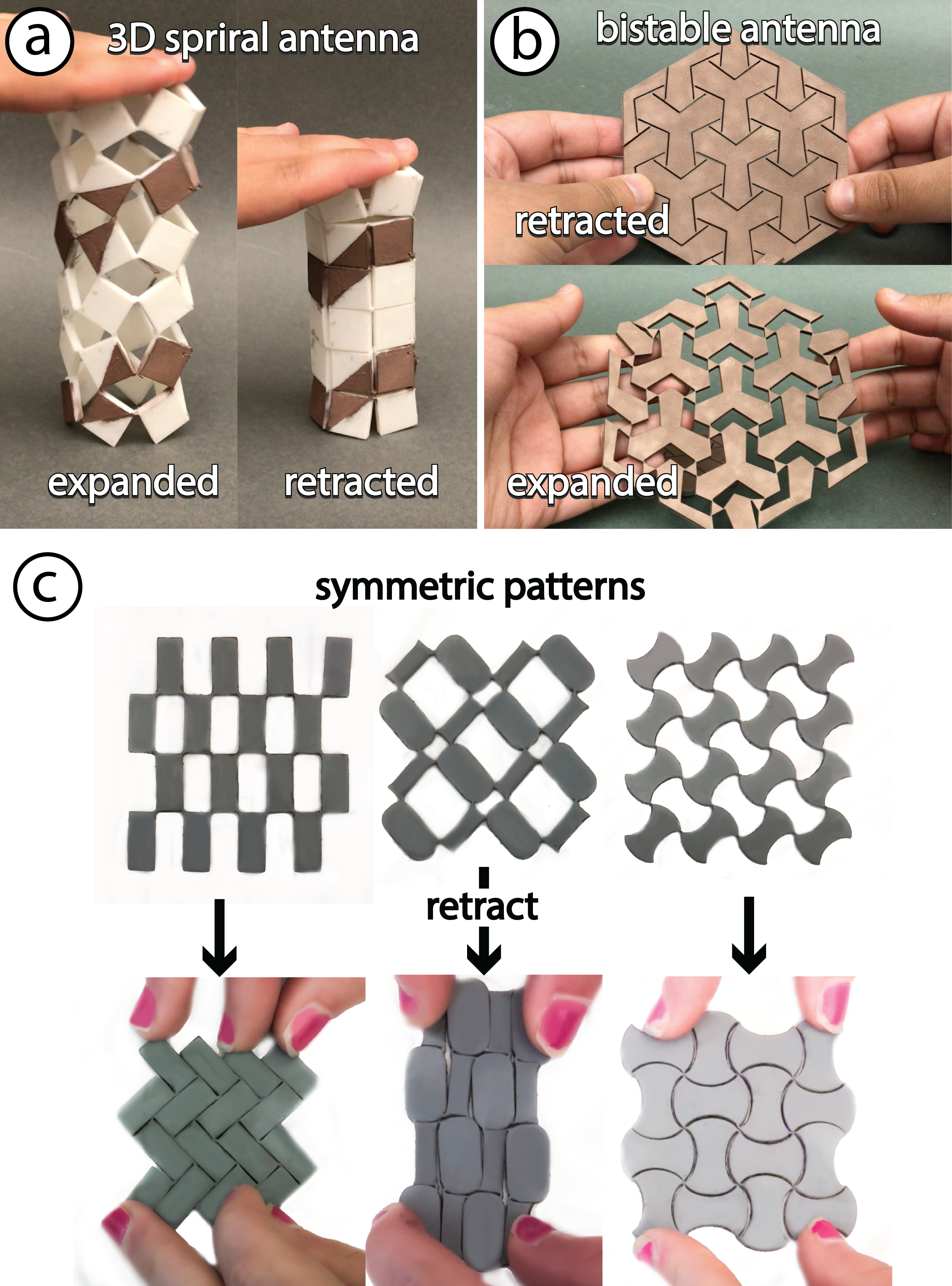
Figure 21. The Meta-antenna design space can be extended to (a) 3D metamaterial structures, (b) bistable metamaterials and (c) other symmetric auxetic metamaterial groups.
Continuous Sensing and State Recognition:
Based on our observations, and motivated by literature on antennas of the same geometry [37], Meta-antenna expansion causes the frequency to linearly decrease due to the increase in the antenna’s effective length. Similarly, for bending, the bend direction and its effect on the effective length also dictate how the resonance frequency changes. For example, [21 ][ 2] show bending increases frequency, while [45] shows a decrease. In future work, we would like to implement continuous sensing and state recognition using ML for Meta-antenna. With our custom patch pattern design, the linear function coefficients of the antenna to be stretched incrementally can be more complicated, which can be combined with machine learning with an ML regression model.
Effect of Direct Human Touch:
During our experiments, we observed that direct contact with human touch affects the resonant frequency of Meta-antenna structures. However, when the human body is in close proximity to the Meta-antenna, yet no direct contact is established, there were no observed changes in the resonance frequency, but slight fluctuations in the return loss db value (SNR). To mitigate the effect of human touch, we can use coating, shielding or air gap structures, which we used for the Hanzi application.
Backscatter:
We demonstrated Meta-antenna with sensing-based interactive applications. Although not demonstrated in this paper, it is possible to implement other interaction modalities, like backscatter, with Meta-antenna by connecting a 50 $\Omega$ load to the Meta-antenna, then connect another antenna to the VNA. The VNA generates a wave and measures how much is reflected back due to Meta-antenna (S11 value). As the Meta-antenna deforms, the other antenna’s S11 value shifts. Backscatter enables wireless power through impedance matching the load to the Meta-antenna via complex conjugates.
Shielding and Environmental RF:
While not implemented and much observed due to using Meta-antenna for sensing, it is possible to mitigate environmental RF noise through proper electromagnetic shielding or more advanced filtering techniques with reasonable compromise over RF communication quality. These methods help isolate unwanted signals, as recommended by literature [13].
Integration with HCI Metamaterial Concepts:
Metantenna relies on surface patterning of conductive material on morphing geometry that change the antenna's effectie length, hence inducing change in the antenna's resonance frequency. This makes Meta-antenna compatible with other Metamaterial concepts in HCI like Metasense \cite{metasense2021}** and Mechanical Metamaterials \cite{ion2016metamaterial}**.
CONCLUSION
In this paper, we presented Meta-antenna, a design and fabrication pipeline for creating frequency-reconfigurable antennas using a single type of mechanical metamaterial structure that can transition between three distinct geometric and frequency states. Our approach offers a straightforward method for creating mechanically reconfigurable antennas with metamaterials, and our technical evaluation shows that our fabrication method produces antennas that radiate efficiently while remaining mechanically and electrically stable after multiple deformations. Through our applications, we demonstrated how Meta-antennas can be integrated into various dynamic objects and across different scales. These applications range from responsive furniture for smart living to adaptive personal electronic devices and interactive tangible user interfaces. Our Ansys-based design tool allows users to design and simulate Meta-antenna structures, while our interaction code template enables user interaction through frequency-shift sensing. Our work demonstrates the potential of combining metamaterials and antennas in a hybridly functional way, paving the way for more means to weave antennas into the fabric of our daily lives. Just as our Meta-antenna serves as both a metamaterial and an antenna, we hope our work inspires further exploration of alternative geometries for antennas and hybridly functional structures.
ACKNOWLEDGMENTS
This project was generously funded by the Bahrain Crown Prince International Scholarship and the GIST-IREF from Gwangju Institute of Science and Technology. We thank MIT Lincoln Laboratory for providing equipment for early testing; Mohammed Al Sheikh for technical insights; Audrey Garon for assistance with early fabrication; and Jiaming Liu for access to his lab’s Prusa 3D printer. We also thank the reviewers for their constructive feedback.
REFERENCES
- Md Abdullah-Al-Mamun, Sham Datto, and Md Shahinur Rahman. 2017. Performance analysis of rectangular, circular and elliptical shape microstrip patch antenna using coaxial probe feed. In 2017 2nd International Conference on Electrical & Electronic Engineering (ICEEE). IEEE, 1–4.
- Nuno Amaro, Carlos Mendes, and Pedro Pinho. 2011. Bending effects on a textile microstrip antenna. In 2011 IEEE International Symposium on Antennas and Propagation (APSURSI). IEEE, 282–285.
- Rosette Maria Bichara, Joseph Costantine, Youssef Tawk, and Maria Sakovsky. 2023. A multi-stable deployable quadrifilar helix antenna with radiation reconfigurability for disaster-prone areas. Nature Communications 14, 1 (2023), 8511.
- Abdelheq Boukarkar, Xian Qi Lin, Yuan Jiang, Yi Jun Chen, Li Ying Nie, and Peng Mei. 2018. Compact mechanically frequency and pattern reconfigurable patch antenna. IET Microwaves, Antennas & Propagation 12, 11 (2018), 1864–1869.
- Taohua Chen, Yueyun Chen, and Rongling Jian. 2019. A Wideband Differential-Fed Microstrip Patch Antenna Based on Radiation of Three Resonant Modes. International Journal of Antennas and Propagation 2019, 1 (2019), 4656141.
- Kuo-Sheng Chin, Chi-Sheng Wu, Chien-Lung Shen, and Kun-Chuan Tsai. 2018. Designs of Textile Antenna Arrays for Smart Clothing Applications. Autex Research Journal 18, 3 (2018), 295–307. https://doi.org/10.1515/aut-2018-0002
- Christos G Christodoulou, Youssef Tawk, Steven A Lane, and Scott R Erwin. 2012. Reconfigurable antennas for wireless and space applications. Proc. IEEE 100, 7 (2012), 2250–2261.
- Gabe Cohn, Daniel Morris, Shwetak Patel, and Desney Tan. 2012. Humantenna: using the body as an antenna for real-time whole-body interaction. In Proceedings of the SIGCHI Conference on Human Factors in Computing Systems (Austin, Texas, USA) (CHI ’12). Association for Computing Machinery, New York, NY, USA, 1901–1910. https://doi.org/10.1145/2207676.2208330
- Joseph Costantine, Youssef Tawk, Jonathan Woodland, Noah Flaum, and Christos G Christodoulou. 2014. Reconfigurable antenna system with a movable ground plane for cognitive radio. IET Microwaves, Antennas & Propagation 8, 11 (2014), 858–863.
- Minhao Cui, Binbin Xie, Qing Wang, and Jie Xiong. 2023. DancingAnt: Body-empowered Wireless Sensing Utilizing Pervasive Radiations from Powerline. In Proceedings of the 29th Annual International Conference on Mobile Computing and Networking (Madrid, Spain) (ACM MobiCom ’23). Association for Computing Machinery, New York, NY, USA, Article 58, 15 pages. https://doi.org/10.1145/3570361.3613272
- I. F. da Costa, Arismar Cerqueira S., D. H. Spadoti, L. G. da Silva, J. A. J. Ribeiro, and S. E. Barbin. 2017. Optically Controlled Reconfigurable Antenna Array for mm-Wave Applications. IEEE Antennas and Wireless Propagation Letters 16 (2017), 2142–2145. https://doi.org/10.1109/LAWP.2017.2700284
- Mariam El Gharbi, Raúl Fernández-García, and Ignacio Gil. 2022. Embroidered wearable Antenna-based sensor for Real-Time breath monitoring. Measurement 195 (2022), 111080. https://doi.org/10.1016/j.measurement.2022.111080
- Edwin Frank and Harold Jonathan. EasyChair, 2024. Mitigating Interference and Noise in RF Communications. EasyChair Preprint 15132.
- Jun Gong, Olivia Seow, Cedric Honnet, Jack Forman, and Stefanie Mueller. 2021. MetaSense: Integrating Sensing Capabilities into Mechanical Metamaterial. In The 34th Annual ACM Symposium on User Interface Software and Technology (Virtual Event, USA) (UIST ’21). Association for Computing Machinery, New York, NY, USA, 1063–1073. https://doi.org/10.1145/3472749.3474806
- Carla Hertleer, Annelien Van Laere, Hendrik Rogier, and Lieva Van Langenhove. 2010. Influence of relative humidity on textile antenna performance. Textile Research Journal 80, 2 (2010), 177–183.
- Andrew Horwood and Nachiappan Chockalingam. 2023. Chapter 2 - Principles of materials science. In Clinical Biomechanics in Human Locomotion, Andrew Horwood and Nachiappan Chockalingam (Eds.). Academic Press, 91–174. https://doi.org/10.1016/B978-0-323-85212-8.00002-X
- Alexandra Ion, Johannes Frohnhofen, Ludwig Wall, Robert Kovacs, Mirela Alistar, Jack Lindsay, Pedro Lopes, Hsiang-Ting Chen, and Patrick Baudisch. 2016. Metamaterial mechanisms. In Proceedings of the 29th annual symposium on user interface software and technology. 529–539.
- Vikram Iyer, Justin Chan, and Shyamnath Gollakota. 2017. 3D Printing Wireless Connected Objects. ACM Transactions on Graphics (TOG).
- Heijun Jeong, Eiyong Park, Ratanak Phon, and Sungjoon Lim. 2022. Mechatronic reconfigurable intelligent-surface-driven indoor fifth-generation wireless communication. Advanced Intelligent Systems 4, 12 (2022), 2200185.
- Srinivasulu Kanaparthi, Veerla Raja Sekhar, and Sushmee Badhulika. 2016. Flexible, eco-friendly and highly sensitive paper antenna based electromechanical sensor for wireless human motion detection and structural health monitoring. Extreme Mechanics Letters 9 (2016), 324–330.
- Tiiti Kellomäki. 2012. Analysis of circular polarization of cylindrically bent microstrip antennas. International Journal of Antennas and Propagation 2012, 1 (2012), 858031.
- Daehwa Kim and Chris Harrison. 2022. EtherPose: Continuous Hand Pose Tracking with Wrist-Worn Antenna Impedance Characteristic Sensing. In Proceedings of the 35th Annual ACM Symposium on User Interface Software and Technology (Bend, OR, USA) (UIST ’22). Association for Computing Machinery, New York, NY, USA, Article 58, 12 pages. https://doi.org/10.1145/3526113.3545665
- Daehwa Kim and Chris Harrison. 2023. Pantundefinednna: Mouth pose estimation for AR/VR headsets using low-profile antenna and impedance characteristic sensing. In Proceedings of the 36th Annual ACM Symposium on User Interface Software and Technology (San Francisco, CA, USA) (UIST ’23). Association for Computing Machinery, New York, NY, USA, Article 83, 12 pages. https://doi.org/10.1145/3586183.3606805