Publication
Xinyi Yang, Katarina Bulovic, Susanna Chen, Junyi Zhu, Stefanie Mueller
Azimuth Calculation and Telecommunication between VR Headset and Smartphones for Nearby Interaction
In Proceedings of
TEI ’23 work in progress.
PDF
Azimuth Calculation and Telecommunication between VR Headset and Smartphones for Nearby Interaction
This paper aims to break the boundary between VR and IoT devices by creating interactions between 2D screens and the 3D virtual environment. Since headsets are expensive and not accessible to everyone, we aim to create a lower boundary for people to take part in the VR world using their smartphones. Existing research mostly focuses on creating new haptic devices for VR, we instead leverage existing IoT devices that people already own, such as smartphones, to make VR technologies more accessible to multiple IoT users. There are two parts in our project: azimuth detection and communication between the VR environment and IoT devices. 1. Introduction Virtual reality breaks the physical boundary by creating an online 3D immersive shared space for people to communicate with each other, providing rich experiences such as social learning [7], occasional meetings[15], pair programming [4], and game streaming [21]. A lot of previous research focused on enhancing the real-time simulations of human physical body and apply them to the virtual avatar [9], creating the haptic devices to interact with each user [20] [3], as well as improving the hardware and the network ability to involve more users in the same virtual environment at the same time. All of these eforts largely beneft the accessibility of virtual reality for general public in daily life. However, many people are still excluded from the 3D immersive environment due to the high price of the VR hardware. The excluded users use traditional IoT devices such as smartphones, tablets, and computers, which do not share the same display and input capabilities as designated VR hardware, so it becomes a major problem hindering the VR environment adoption. Therefore, asymmetric VR is recognized as "a legitimate way to expand the reach of VR in the consumer market" [17]. We identify the following two important aspects to enhance the development of asymmetric VR interaction: (1) localization, which helps the users in the VR environment locate the users that are using the IoTs in real-time when they share the same indoor space, and (2) information transformation, which helps the VR users and the IoT users communicate and interact on their own interface simultaneously. Existing methods for spatial object localization and positional tracking in virtual reality are to use markers of the objects and the cameras, which are embedded in the VR headsets. Some other novel ways including the use of WIFI [11] or the combination of lasers and sensors [10] for localization in the context of virtual reality.We want to explore an alternative way for localization by getting rid of the camera, which can protect the users’ privacy by not getting the recordings of the real scenes, while ensure the accuracy of location detection. Moreover, we try to make the minimum modifcation of the existing VR hardware to make the technique more accessible. On the other hand, how to connect VR users and IoT users is not yet throughly explored by VR researchers and developers. Therefore, by solving these two issues, we can provide users with a "crossplatform" seamless interactive environment. Developing these two design goals into features requires access to the underlying VR software and hardware stacks. In this research, we embed ESP32 UWB modules in the VR headset and smartphone to achieve the azimuth calculation between VR users and IoT users. At the same time, we use WIFI to transfer the data between the 2D screens and the 3D immersive environment. Our main contribution includes:- Conducting the azimuth calculation experiments using ESP32 UWB modules and fguring out the distance range between the "tags (smartphone)" and "anchors(VR headset)", as well as the distance between two "anchors( the distance between two ESP32 modules in the VR headset)";
- Deploying an interactive game as a proof of concept based on the data from the above experiments;
- Pointing out our future work for integrating this technology into diferent IoT devices besides smartphones.
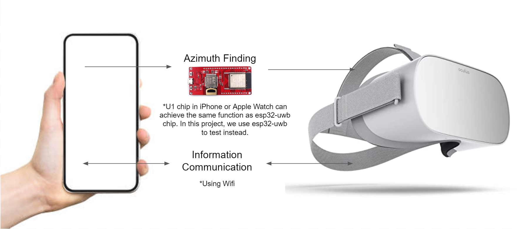
Figure 1: Two Parts of the research: Azimuth calculation and information communication across the VR headset and smartphones
2. Background and Related Work
This section presents the background work which includes asymmetric VR interaction, and wireless indoor localization and tracking.
2.1 Asymmetric VR interaction systems
The concept of asymmetric interaction refers to “the capacity of individuals in a group to have diferent means to visualize and interact with virtual content" [6] [16]. By breaking down the boundary between the HMD (Head-mounted Displays) and non-HMD platforms, users can choose alternative devices, apart from VR headsets, to access the virtual environment based on their own preferences. More importantly, more people can access the same virtual environment simultaneously, even though they have limited VR headsets in the shared space. In the paper of Kaitlyn [16], it points out that to achieve the co-located asymmetric VR, there are fve important parts in the framework, including spatial co-presence [12] [2], transportation [12] [2], informational richness [14], team interdependence[2], and balance of power. In this paper, we focus on the "transportation" part of the asymmetric VR systems by building a telecommunication framework, which can provide more freedom for future researchers and designers to build the interfaces on top of our techniques.
2.2 Wireless indoor localization and tracking
Indoor navigation and route-fnding have various use cases, such as gaming, tracking items, delivery of goods and robotics. There are diferent techniques for wireless indoor localization, including WIFI [8], NFC (Near-feld communication technique) [18], BLE (Bluetooth Low Energy technique) [13], ultrasonic system (with the combination of concurrent radio)[19], cameras [5], as well as LIDAR [1]. In this paper, we focus on exploring how to detect the angles between the target object (the IoT users) and two antennas that are mounted on the VR headsets by using an ultra-wideband radio(UWB) system. The reason we choose the UWB system is its capability of transmitting information across a wide bandwidth (>500 MHz). This allows transmitting a large amount of signal without interfering with conventional narrowband and carrier wave transmission in the same frequency band.
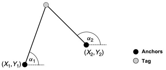
Figure 2: Triangulation: the angulation method for indoor localization and tracking in our research. Anchors represent two antennas (hardware that is mounted on VR headsets), and the tag represents the receiver (IoT device). The ESP32 UWB modules are commercially available.
3. Techniques
In this session, we discuss how to achieve azimuth calculations for our asymmetric VR interaction system, which is the key issue for our technique. Incorrect measurement of the distance between the tags and the anchors can result in the wrong calculation of the angulation. However, no existing literature has studied the optimal distance between two anchors and the performance of using UWB in VR settings. So we set up the following experiment.
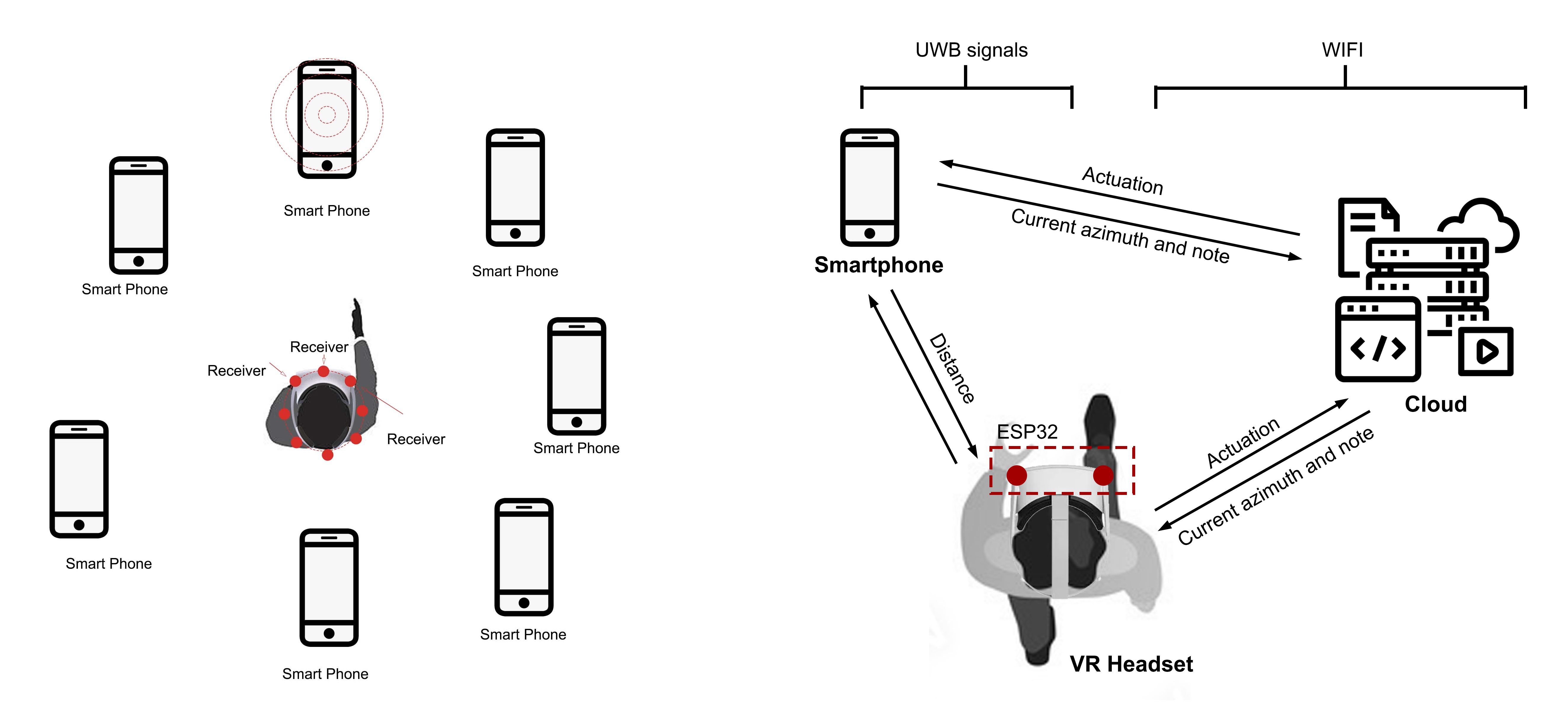
Figure 3: Concept and design system. On the left: we envision that with our techniques, the VR users and the smartphone users can interact with each other not just in virtual reality with the sense of physical position; On the right: System framework for the technique. We use WIFI to transfer the data between users and Ultra-wideband radio system to get the correct physical position.
There are two main procedures in our calculations: (1) Getting the distance between "anchor 01" and the "tag", as well as the distance between "anchor 02" and the "tag", and (2) Getting the angulation between the "tag" and the center-line of two "anchors". Detailed calculations procedures are as following [Also see Fig.4]:
-
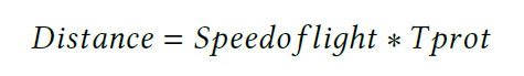
Getting the distance between the "anchor" and the "tag": When the setup starts, the anchor sends the message (TX) and has a record of the time Mark. After that, the tag gets that message and has the record of the time Mark too. After the delay (Treplay), the tag sends the message (TX) and has a record of the time mark, and fnally, the anchor also receives the message and has the record of the time mark. Then the anchor gives feedback again to the tag. Therefore, the calculation equations are as follows:
(1) Basic principle (Calculating the distance using the fight time):
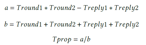
 (2) Actual calculation through our measurement using double-sided two-way ranging:
-
Getting the angulation between the "tag" and the centerline of two "anchors": From the above calculation, we get two distances from the "anchor" and the "tag" as "range1" and "range2". Then we calculate the azimuth θ of each phone (angle relative to the VR headset). The calculation steps for getting the angles between the "tag" and the "anchors" are as following:
(1) Calculate γ using the law of cosines (we know the side lengths range1, range2, and d from the above calculation and the experiment setup);
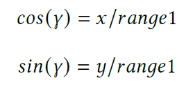
(2) Calculates (x, y) using trigonometry:
 (2) Calculates θ using trigonometry:
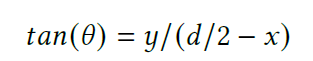
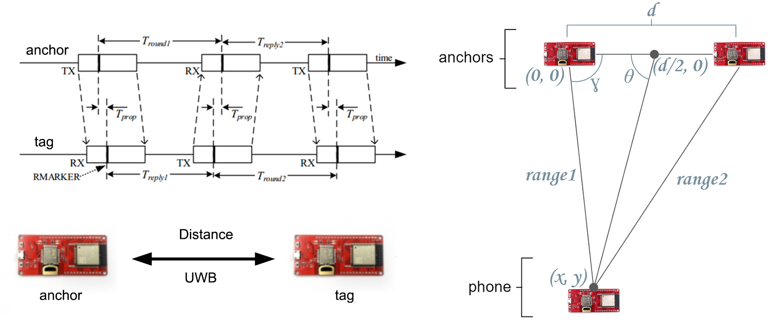
Figure 4: The diagram for the calculation of the distance be-tween the "tag" (on the left) and "anchors" and the calculation diagram for the angle from the "tag" to the center line of two "anchors" (On the right).We build the Arduino code based on the library that the manufacturer provided for our research.
4. Evaluation Metrics
For our evaluation, we focus on measuring angular resolution to determine the direction of the smartphones. We measure angular resolution versus the separation between two anchor ESP32s (which act as antennas), as well as the angle resolution versus the distance from the anchors to the smartphone.We measure the distance from anchors of 2m, 4m, and 6m, and the distance between anchors of 30cm, 50cm, and 70cm. The reason we choose this setting is to adopt our technique in our VR headset without additional hardware modifcations. If the distance between two anchors is too large (e.g., > 70cm), it is hard to integrate them into the existing VR headsets. And we measure the data with the clockwise angle from the left side of 30°, 60°, 90° [See Fig.5]. We assume that we can get the same results of 120°, 150°, and 180° as it is the mirror settings of the experiment.
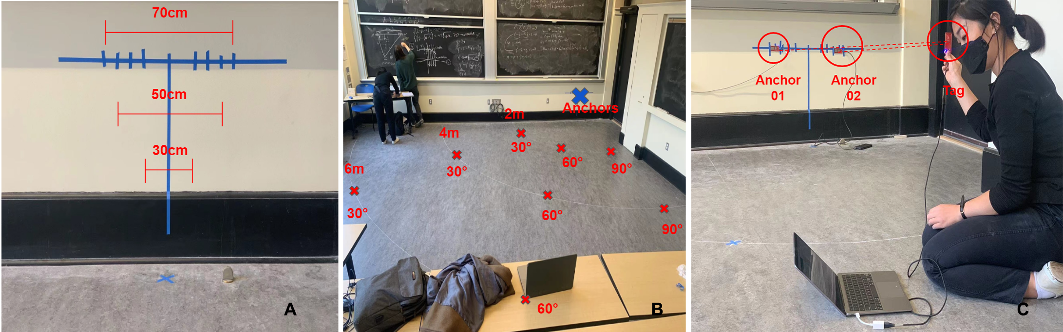
Figure 5: Experiment setup. A.We attached two ESP32 UWB modules as two "anchors" on the wall with diferent distances;
B. The experiment environment (we measure the distance from the anchors of three diferent distances with three different angles. C. One person hold the "tag(another ESP32 UWB module)" at a certain point to get the data from the laptop.
5. Results
For the smartphone angular measurements, we expect that as the anchors move farther apart, the angle resolution will decrease (improve). We also expect that as the smartphone moves farther away from the anchors, the angle resolution will increase. Overall, this data can help us to fgure out a working system that creates an integrated and streamlined experience between smartphone users and VR. Through the experiment, we achieve the following three important fndings [See Fig.6 - 7]:
- Accuracy and precision improves as anchor separation increases and distance from anchors decreases;
- Users (i.e., phones) should remain closer (within about 4m) for the best results, and the angular measurement is most accurate when the phone is close to 90 degrees (right in front of the VR user). The highest error range we measured was with the phone 6m away at a 30-degree angle, which had a standard deviation of approximately 10 degrees;
- 50cm anchor separation works best for the purposes of our project. As we can see from the data and the fgures below, there are not much diferences in the accuracy of 50cm or 70cm anchor separation (with 70cm being slightly better). However, when considering the size of the IoT device, it is better to use a 50cm anchor separation.
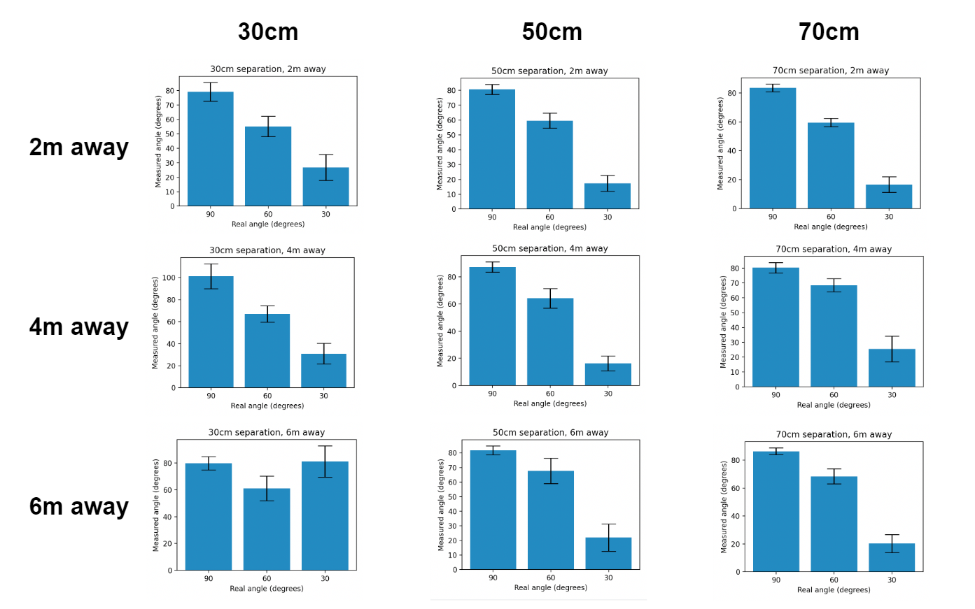
Figure 6: The accuracy of the azimuth calculations in our experiment.We measured 200 times at the same position to get the detected angles from the "tag" to the "anchors" and thus have the average as well as the range of the angles at the same position. In summary, the range of the detection data gets smaller and smaller when the distance between two "anchors" is larger, and the distance between the "tag" and the "anchors" is smaller. B. The experiment environment (we measure the distance from the anchors of three diferent distances with three different angles. C. One person hold the "tag(another ESP32 UWB module)" at a certain point to get the data from the laptop.
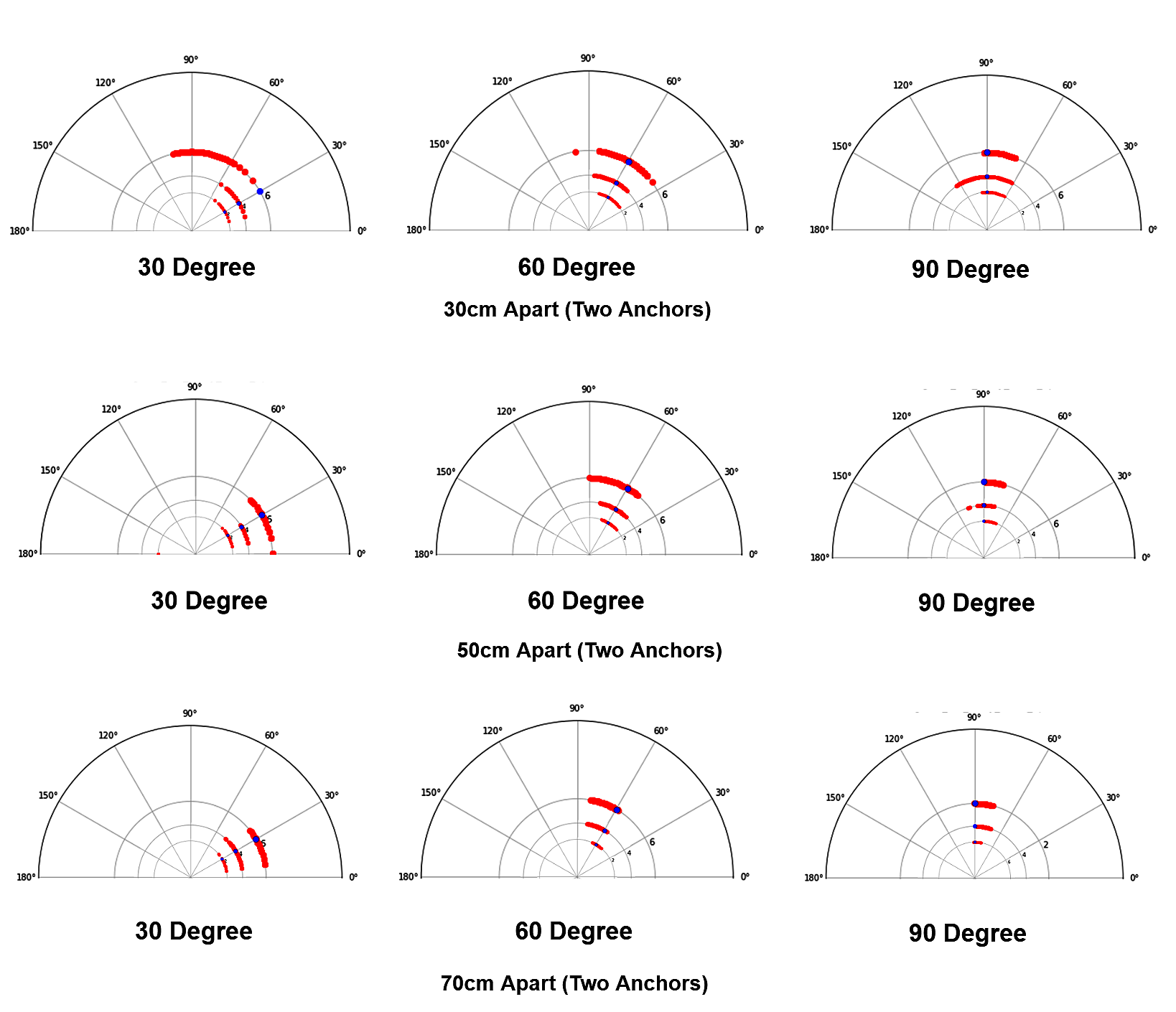
Figure 7: When the distance between two anchors is 30 cm, the data shows that it can not efciently detect the correct directions of the tag, especially when the "tag" is far away from the center line of the "anchors". When the distance between two anchors is 50 cm, the data gets better when compared with the data that we get from the "30cm" experiment. We can get more accurate data of the direction of the "tag" compared with the data that we get from the "30cm" and "50cm" separation between the "tag" and the "anchors". However, the improvement of the accuracy is not as much as the improvement from the "30cm" separation distance between "anchors" to "50cm" one. B. The experiment environment (we measure the distance from the anchors of three diferent distances with three different angles. C. One person hold the "tag(another ESP32 UWB module)" at a certain point to get the data from the laptop.
6. Applications
We have deployed an interactive game as a proof of concept. For the hardware part, the system includes three main components: the user’s smartphone, VR headset, and ESP32 UWB for azimuth detection. Two “anchor” ESP32s are mounted on the headset with a distance of 50cm between each other and one “tag” ESP32 is attached to a smartphone. For the distance of two "anchors",we used the optimal data (50cm) that we get from the above experiment. For the software part, the VR headset can receive and visualize which direction each user is in and receive information (in this case, the tone of the sound) that is sent from their smartphones. Additionally, the VR user can send information (in this case, the tone generated from the target smartphone) to be received by smartphones. Then, we send azimuth data from the “tag” (the one mounted on the smartphone) to the VR headset over a WIFI connection. [See Fig. 8 -10]
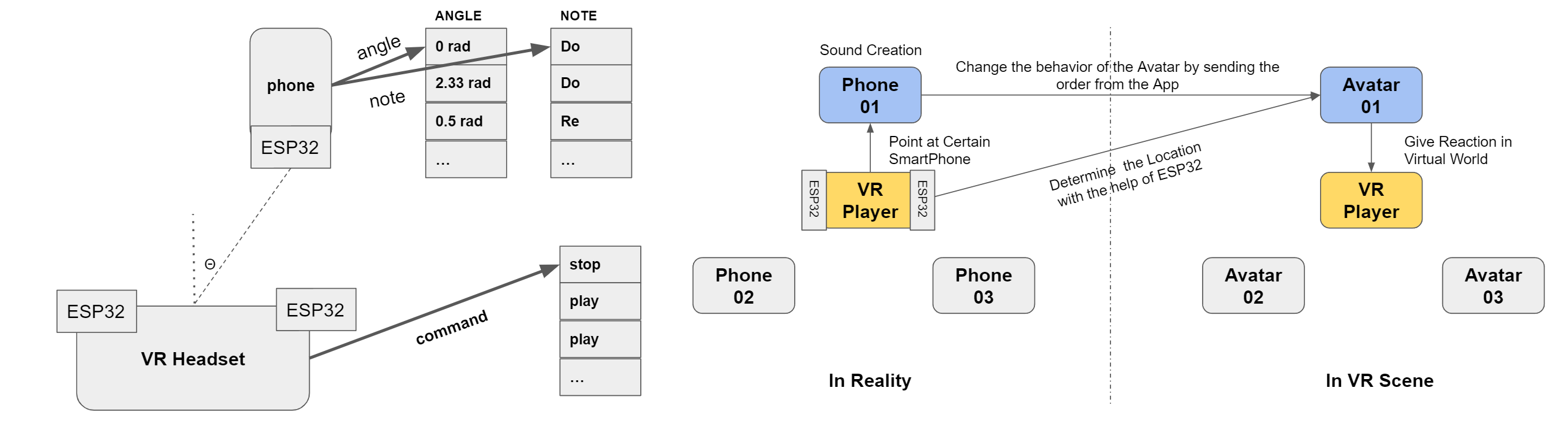
Figure 8: General principle and system for our interactive game. On the left: The basic setup in our games: on the smartphone side: it can calculate the angle from VR ESP32 and people can use the smartphone to change notes; on the VR side: determine when the smartphone should play and the avatar changes location based on the location of the smartphones; On the right: the whole games can include more than one IoT users.
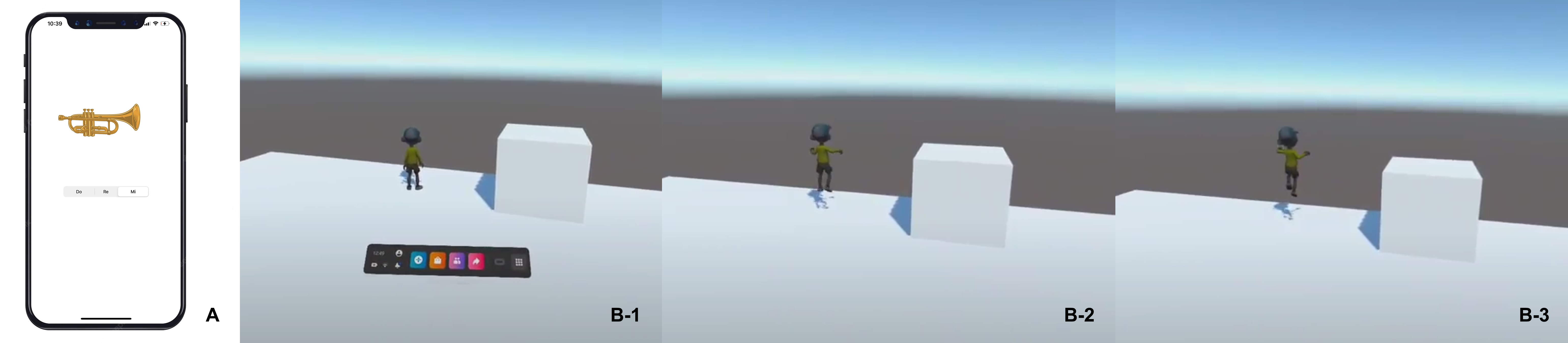
Figure 9: Test Demo: A: Our user interface on smartphones(Users with smartphones can play diferent tones (Do-Re-Mi) by clicking the button on the screen then the sound will be played in the 3D environment(VR headset). B: And at the same time, the avatar in the 3D environment will move to the same position where the user points at.
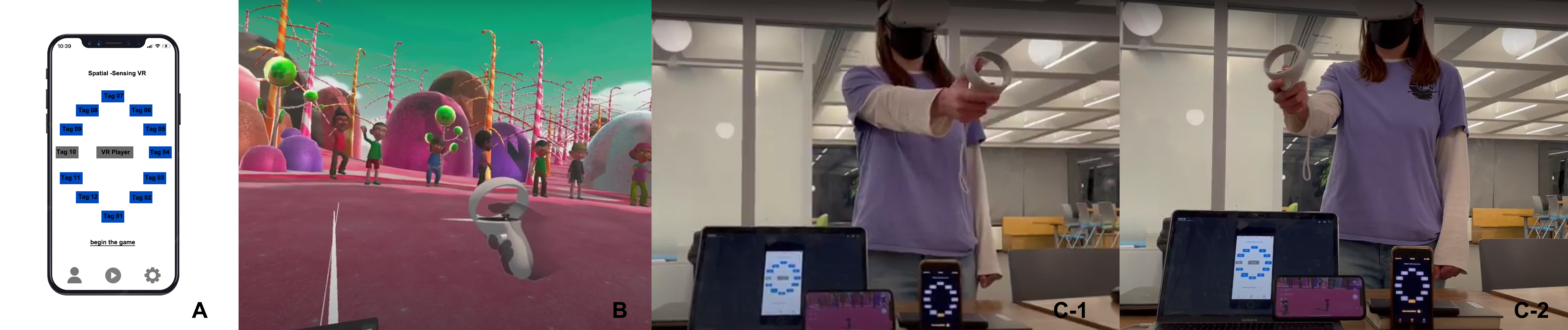
Figure 10: Final Demo: We also create a playful environment with diferent avatars to allow all the players using either VR headsets or smartphones to have an interactive game. (A: the user interface for the users who use the iPhone/IPad/Macbook; B: the 3D immersive environment for the VR player; C: the real world environment the player is playing with our interactive game.)
7. Discussion and Future Work
In this section, we discuss the limitations of our approach and lay out directions for future work.
- Making a comparison of the performance between our proposed technique and other existing tracking systems, such as HTC Vive lighthouse, and Oculus’ inside-out-tracking system.
- Researching on how to measure the distance between IoT devices (i.e., smartphones) and VR headsets. The existing technique can detect the direction of a certain user by the VR headset, but we haven’t discussed how to get the distance between the users in this paper.
- Exploring ways to use the existing hardware in IoT devices instead of using an additional ESP32 UWB module that is attached to the device. Nowadays, many IoT devices such as Apple devices, have already included U1-chips for nearby interaction, which can achieve the same function as the esp32-UWB modules.
- Conducting another experiment with multiple "tags" (devices) / multiple "anchors" (VR headsets) to analyze the feasibility of multiple users joining our system. The proposed technique allows one VR player to interact with multiple smartphone players in the demo games. In the future, we want to test the maximum capability of the number of players in our own system.
- Extending the techniques to other IoT devices. To make our technology more accessible, we will create more applications to prove that our concepts can be achieved via diferent IoT platforms such as desktops, tablets, watches, etc. And we will study how diferent platforms can collaborate seamlessly with the same VR 3D environment simultaneously.