6.810 Engineering Interactive Technologies (fall 2021)
Lab1: Circuit Drawings for Conductive Inkjet Printing
In this lab, you will first create the circuit drawing for your music card and then print out the circuit using conductive inkjet printing.
Steps:
- Install Drawing Program and Download Visual Design File
- Add Touch Button, Wires, and Connector Pads
- Add Touch Slider Segments, Wires, and Connector Pads
- Verify your Design
- Export your Design
- Print the Circuit
- Print the Visual Design
- Laminate your Circuit Design
Deliverables:
At the end of the lab, upload to your student google drive:
- the Adobe Illustrator drawing file (combined-visual-circuit.pdf) that contains both your circuit and your visual design on two separate layers
- the two individual pdfs (circuit-design.pdf and visual-design.pdf) you used for printing
- two photos showing the front and back of your inkjet printed card
Help us Improve Class Materials for Lab1:
Please let us know if you had any trouble with the fabrication devices or if anything was confusing in the write up.
You can add your comments here.
Before you start
Sign-Up Spreadsheet: Don't forget to fill out the 6.810 sign up spreadsheet to enroll in class.
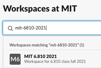
Join 6.810 Slack Workspace: To join the 6.810 workspace, first click here and sign in with your kerberos. On the following page, type in 'mit-6810-2021', which should show the 6.810 class workspace. Join the workspace. We recommend you install the slack desktop app and access the workspace from there.
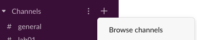
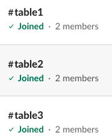
 Join Slack Channels for 'Lab01' and your table number, e.g. 'Table1': When you join slack, the channels are not yet visible to you. You need to click on the little '+' next to the 'Channels' side bar and then 'browse channels' to see all channels. For now it's enough to join the 'Lab01' slack channel (for general announcement related to the lab) and your respective table's slack channel, e.g. 'Table1' (for asking for TA/LA help and sharing info with other students at your table).
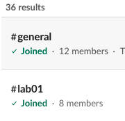
 EECS Safety Acknowledgement Form: Please read the EECS electrical safety form and then sign at the bottom. We don't do any electrical work in lab1, so no need to do it right away, however, you need to fill it out before you start lab2. In case there is a line at the printers, maybe you can use the time to do the form.
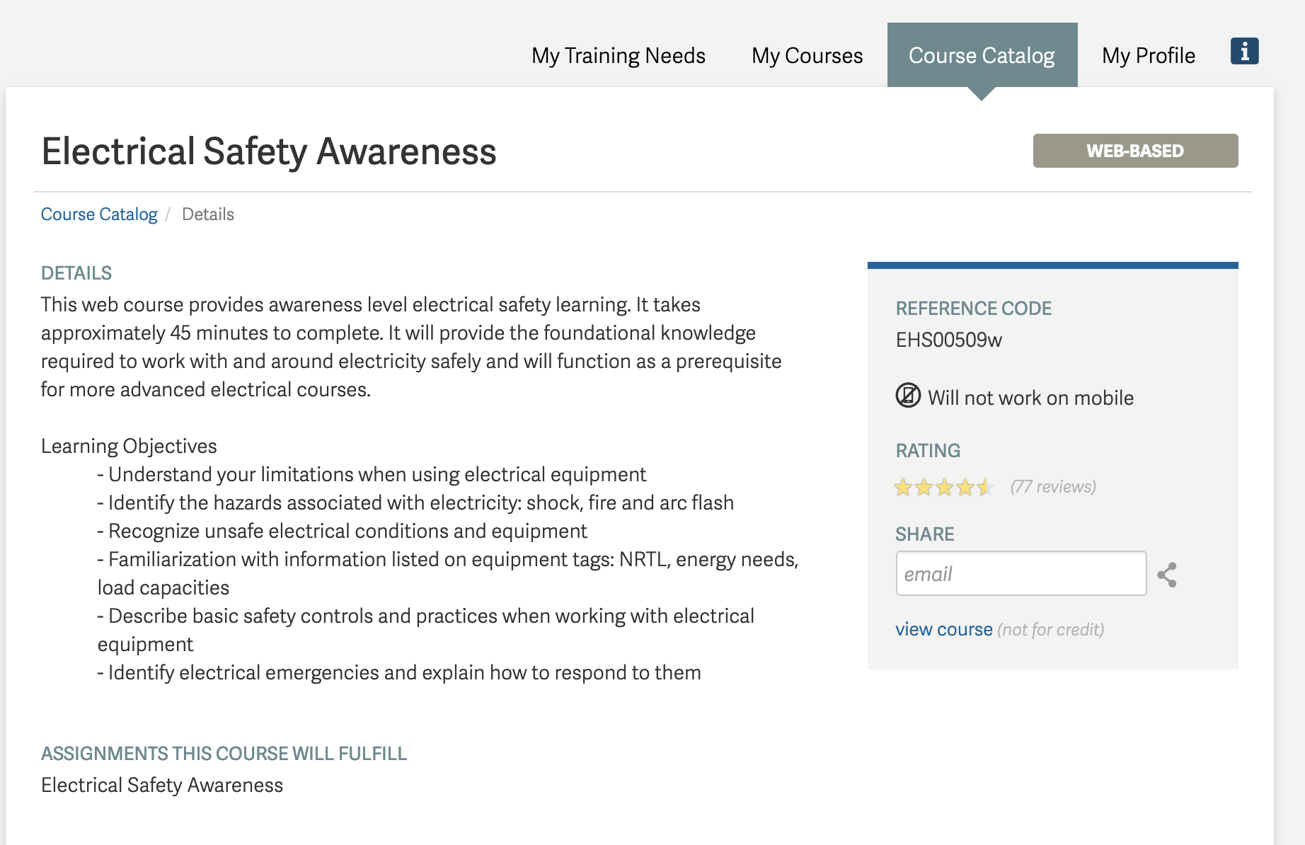
EECS Safety Training on ATLAS: You also need to do the EECS electrical safety training on ATLAS. Similar to the training above, you don't need it for lab1, but you need to do it before lab2 (training takes about 40 minutes). To find the training, go to ATLAS, then click 'Home' and in the sidebar 'Full Menu'. In the search bar, type in 'Learning Center' and select it. On the new page, click on 'Course catalog' and search for 'EHS00509w'. Then select the 'Web-based' version.
EECS Safety Acknowledgement Form: Please read the EECS electrical safety form and then sign at the bottom. We don't do any electrical work in lab1, so no need to do it right away, however, you need to fill it out before you start lab2. In case there is a line at the printers, maybe you can use the time to do the form.
EECS Safety Training on ATLAS: You also need to do the EECS electrical safety training on ATLAS. Similar to the training above, you don't need it for lab1, but you need to do it before lab2 (training takes about 40 minutes). To find the training, go to ATLAS, then click 'Home' and in the sidebar 'Full Menu'. In the search bar, type in 'Learning Center' and select it. On the new page, click on 'Course catalog' and search for 'EHS00509w'. Then select the 'Web-based' version.
 Now that we have the logistics out of the way, let's get started with the actual lab.
(1) Install Drawing Program and Download Visual Design File
Download and Install Drawing Program: We recommend to use Adobe Illustrator. All MIT students have access to free Adobe Creative Cloud licenses here. All our instructions will be based on Adobe Illustrator. If you use a different drawing program that's fine but we may be less knowledgable on how to use it and may not be able to help you as much.
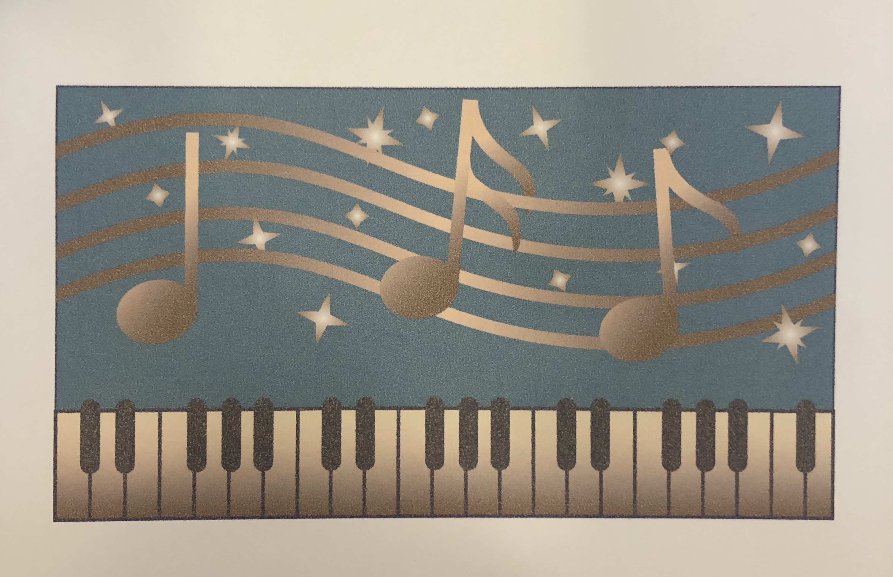
Download and Open Visual Design File: To get started, download the visual design file for our music card here and open it in your drawing program. Alternatively, you can also make your own design. Please see the left side bar to decide if you want to go down that route.
Adjust the Document Settings to mm: Once you opened the design file, adjust the document settings by clicking on Edit->Preferences->Units and set all units from 'pts' to mm.
(2) Add Touch Buttons
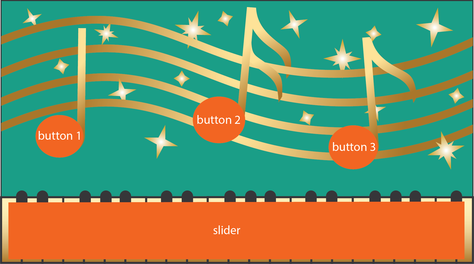
For our interactive card, we want to add three touch buttons, one on each note (we will later use them to go to the next and previous song and pause/play the song). Touch buttons consist of one shape + one wire + one connector pad. One end of the wire connects to the touch button shape and the other end connects to the connector pad which will in turn connect to the microcontroller.

Video Tutorial: Below, you'll find a video tutorial that shows you all steps to add one touch button. Your task will be to add all three touch buttons on top if the notes.
Create a New Layer: Start by creating a new layer in your design file. You need to create the circuit design on a separate layer than the visual design because later you need to export two files separately, the visual design in one .pdf and the circuit design in a separate .pdf. Using a separate layer for each allows you to turn each part of the design on/off quickly for export.
Draw the Touch Button Shape: Once you created your circuit design layer, draw the first touch button on it. A touch button should be large enough for a user's finger. The size of a finger tip is roughly an area of 2cm x 2cm. In the design we gave you, the size of each note body is roughly the size of a finger pad, so as long as you make a shape the size of the note it should be fine.
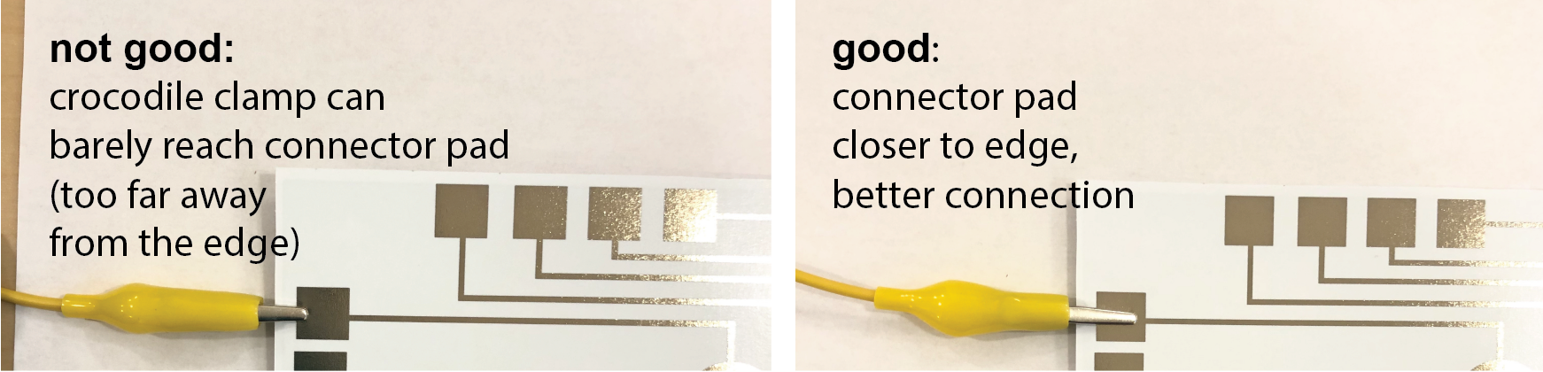
Draw the Connector Pad: In order to connect the touch sensor to your ESP32 microcontroller later, we have to add connector pads at the edge of the music card. We recommend to place all the connector pads for the touch buttons on one side of the card (we will later draw more connector pads for the slider, so leaving another side free will ensure we will have enough space later). The connector pad for the microcontroller needs to be large enough to connect to a crocodile clamp. Therefore, the connector pad should be 10mm x 10mm. Make sure your connector pads are close enough to the border of the card so that a crocodile clamp can reach it (we recommend to place them less than 5mm away from the card border). Make sure to not exceed the boundaries of the music card since we will later cut it out.
Draw the Wire: Next, draw a wire from the touch button to the connector pad. Your wire should be 1mm thick. The thickness of the wire determines its conductivity (larger cross-section == higher conductivity). With 1mm we are on the safe side given the conductive ink we use and its resistance. Make sure that all wires are located inside the boundaries of your card since we will later cut out the card.
Repeat all steps for the other two touch buttons.
(3) Add Touch Slider
In addition, the piano area should serve as a volume slider, i.e. if we drag our finger from left to right, the volume of the music that is playing will increase.
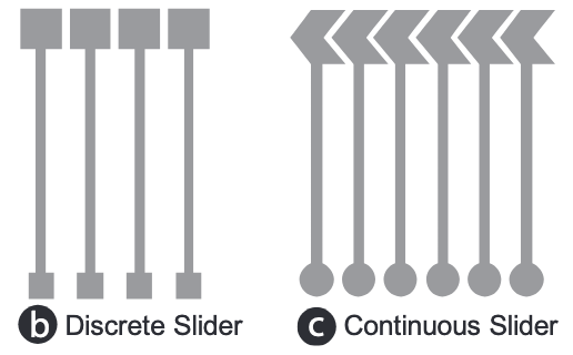
Discrete vs. Continous Sliders: Touch-sliders consist of multiple touch buttons linearly arranged, i.e. several segments and each segment has its own wire and connector pad that connect to the microcontroller. In the discrete slider design, the finger is only over one of the slider segments. In the continous design, the finger touches two adjacent slider segments. By knowing how much the finger touches each slider segment, we can extrapolate continuous transitions between the segments. We will create a continuous slider, i.e. the segments overlap.
Slider Resolution: The slider resolution depends on the number of slider segments. More slider segments allow for higher resolution but since each slider segment needs its own wire, connector pad, and pin on the microcontroller it can quickly add up. For our purposes, we will create 5 slider segments.
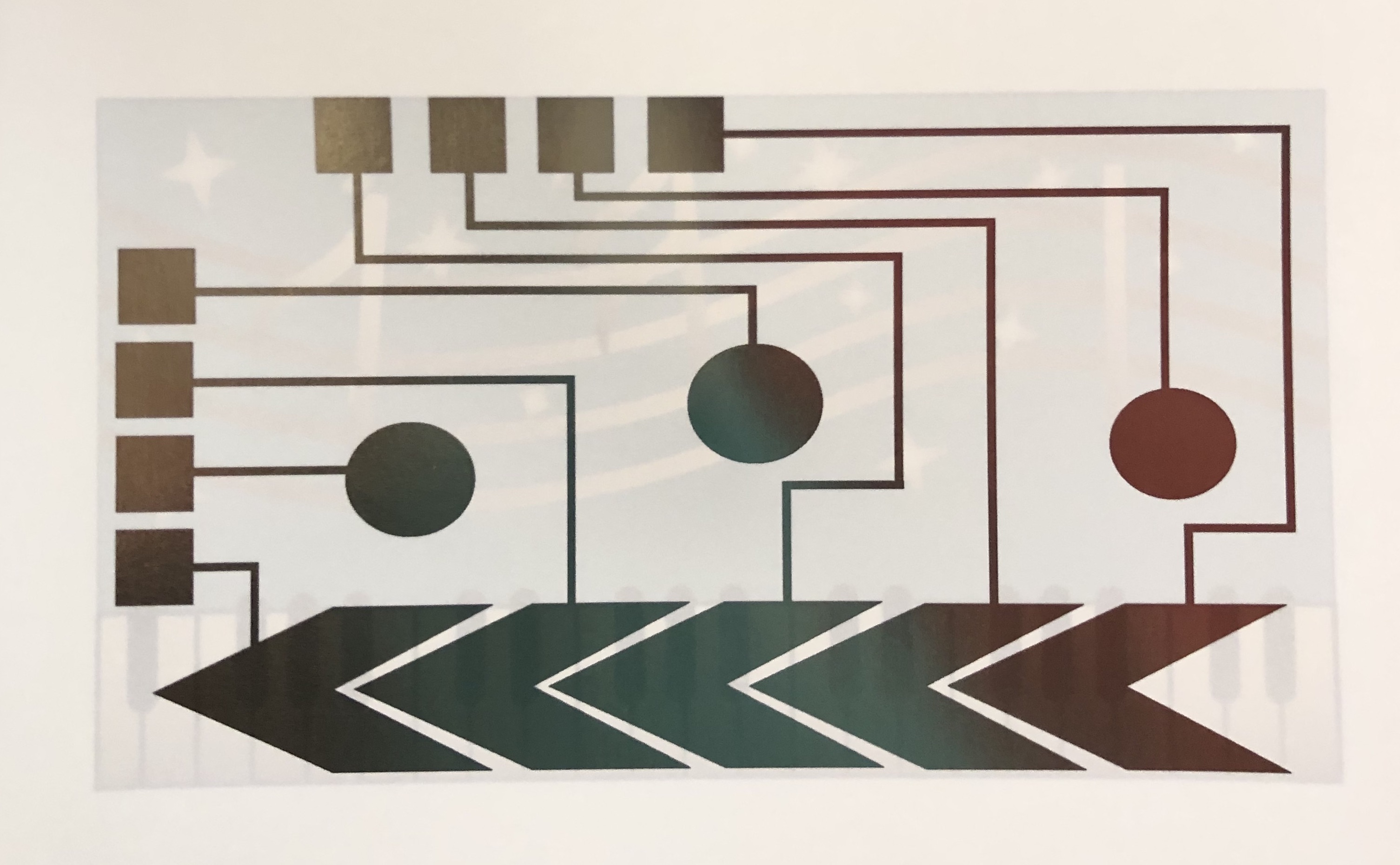
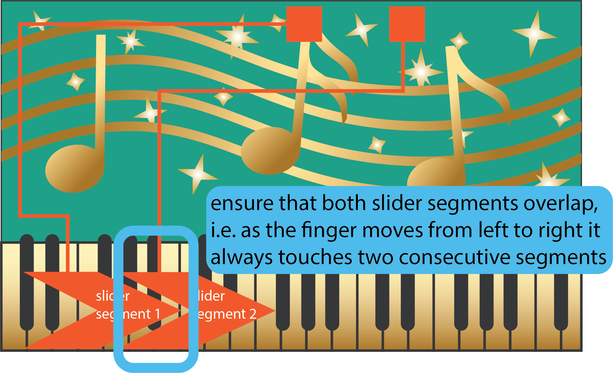
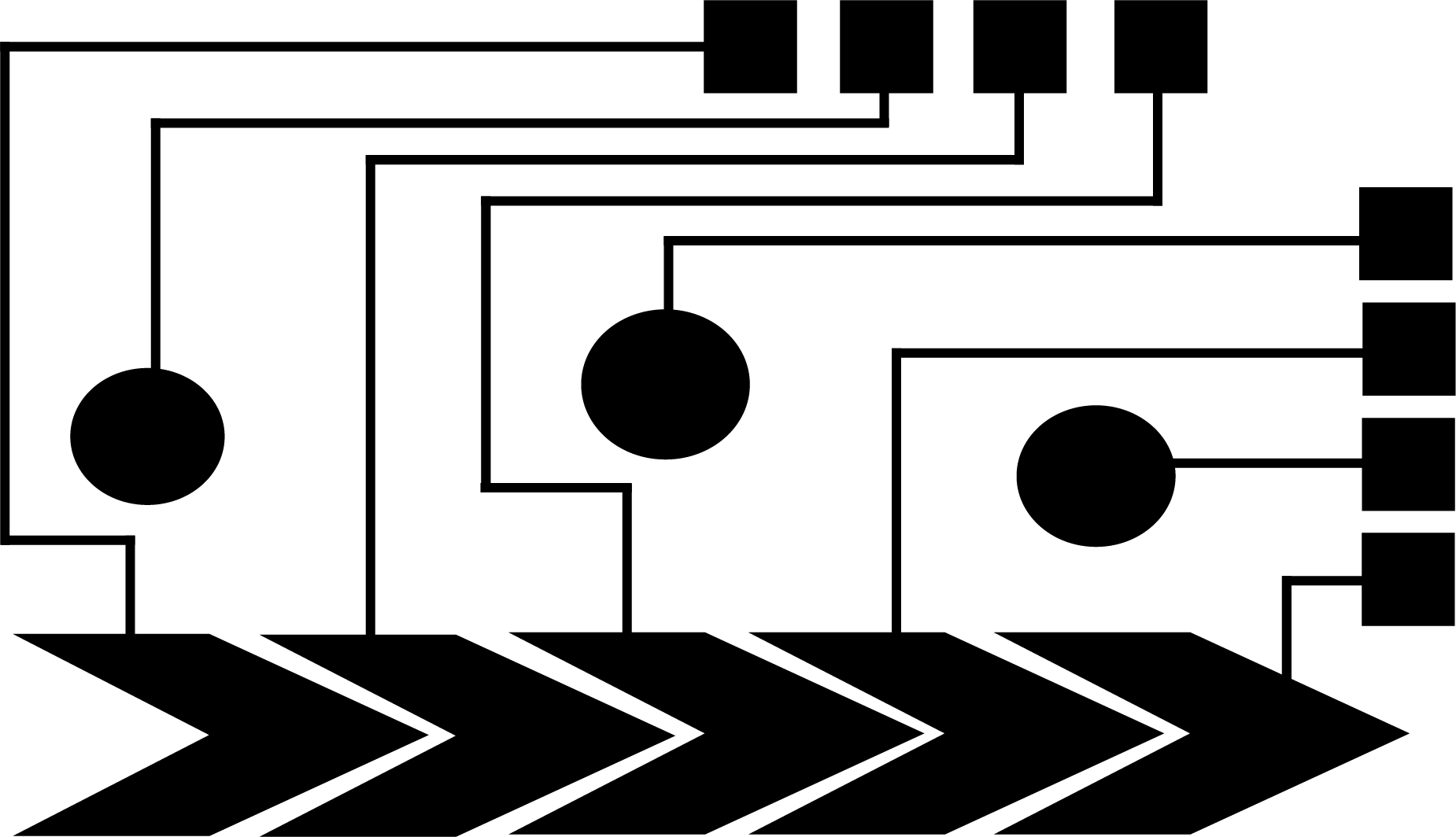
Draw the Slider Segments: Let's draw the slider segments, as well as their wires and connector pads. Below you see an image that already has two slider segments marked up, you need to divide the remaining 'piano' area to form another three slider segments and connect them via wires to additional connector pads. When you draw your slider segments, pay close attention that each slider segment overlaps with each other, i.e. you can see in the image below how the front of the first segment reaches deep into the second segment to maximize overlap. For the wires and connector pads for each slider segment, follow the same specification as before, i.e. use 1mm for wire thickness and 10mm x 10mm for connector pad size. For the spacing between slider segments use 2mm, this brings the slider segments as close as possible together without risking that they intersect.

Video Tutorial: In this video tutorial, you will see how to create a slider segment and how to ensure a certain distance between them.
(4) Verify your Design
Before printing out your design, let's double check that everything is correct. Below are some of the most common issues we have seen last year:
Drawing in pt instead of mm: Make sure your drawing is in 'mm' not 'pt'. You can check this if you go to Edit->Preferences->Units.
Visual Design & Circuit Design Not Centered on Page: Make sure your circuit drawing is centered on the page. If it is not centered and you print it out, your visual design and your circuit design will not overlap, i.e. your touch button will not be underneath the note. To check if your circuit drawing is centered, select your entire design and check if its x-coordinate is '107.95mm' or 4.25".
Gaps along wires: Zoom into your drawing and make sure all your wires are connected, sometimes there are tiny gaps that you don't see in zoomed out mode. If you have a gap, your wire will not work. Check: (1) Is each wire connected to its corresponding touch buttons/slider segments? (2) Is each wire connected to its connector pad? (3) If your wire consists of multiple individual drawn rectangles, are they all connected to each other?
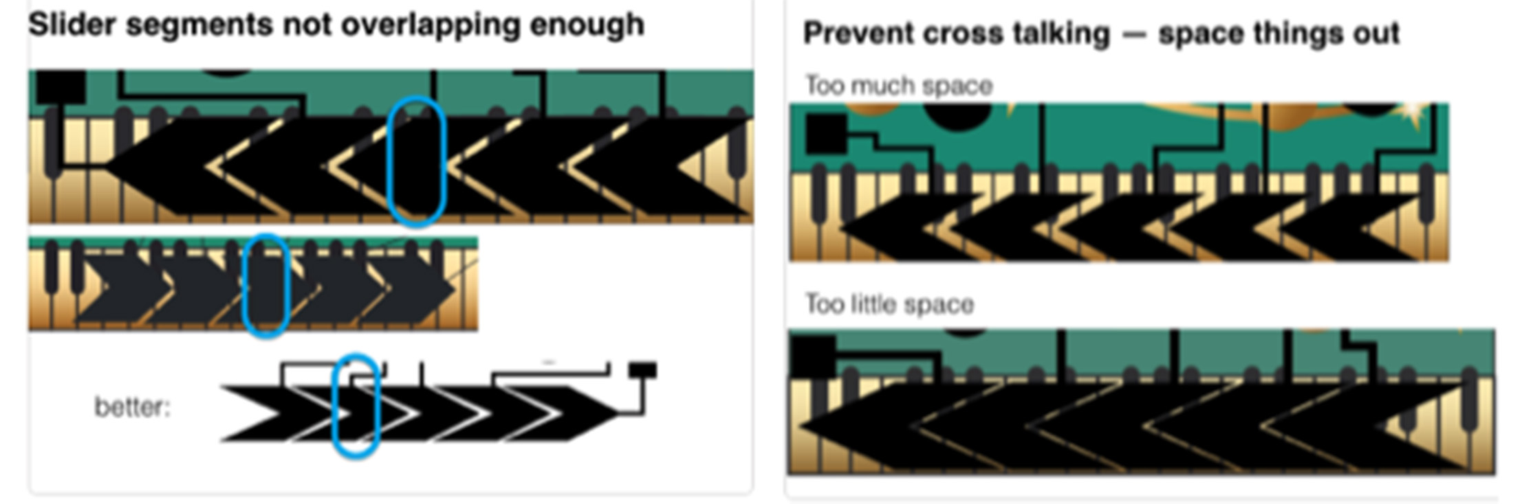
Wires routed too close to Touch buttons/Slider Segments: Make sure you leave sufficient space between the wires and the touch buttons and slider segments. If they are too close to each other there can be cross talk, i.e. touching one button can create a signal on a close-by wire of another button, which then also detects that it was touched.
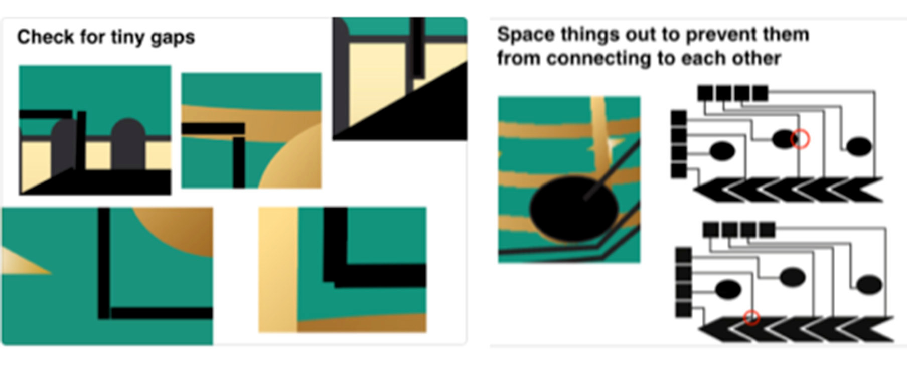
Slider Segments not overlapping enough: Finally, your slider segments should be close together. If they don't overlap enough, your finger will only touch one of them, which will not result in a continous slider signal. Aim for a distance of 2mm between slider segments.
Slider Segments too close to each other: Make sure there is sufficient space between each slider segment. If they are too close, you will also have problems with cross talk, i.e. touching one slider segment will automatically activate the other as well. Aim for a distance of 2mm between the segments.
Check your design for no overlapping wires and connector pads: After printing the card, you will cut it out. Check that all your silver traces are within the boundaries of the card design otherwise you will cut them off.
(5) Export your Design
Now that you have verified your design, you are ready to export and print it. Since for capacitive touch sensing, the user should never touch the silver directly, we will print the circuit design on one side of a piece of paper and the visual design on the other side.
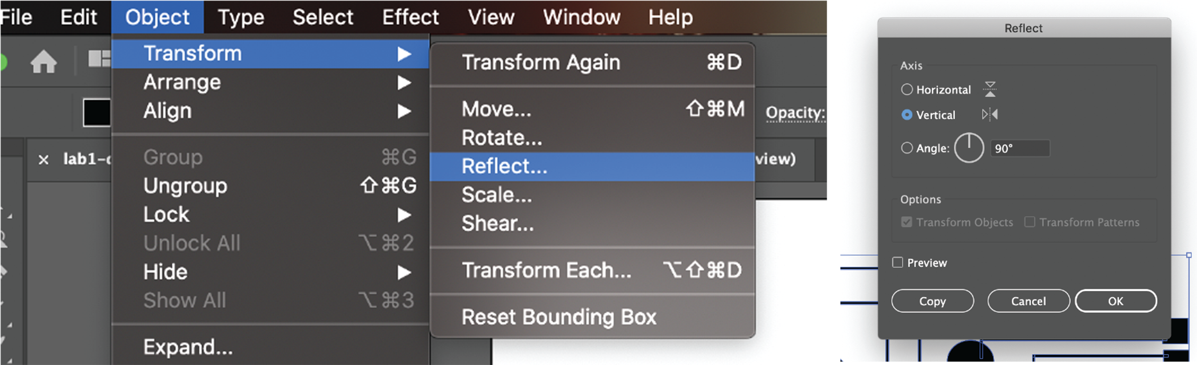
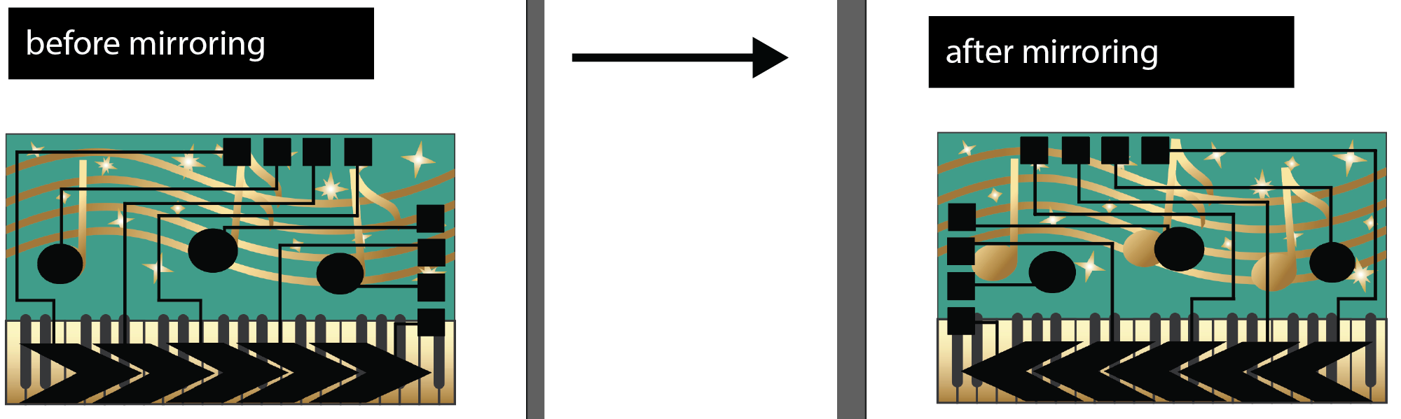
Mirror the Circuit Layer: In order to accommodate the double-side printing, we will need to mirror the circuit design, otherwise if we flip the sheet for printing the touch buttons and the notes will not align. We don't want to mirror the visual design since it would look very odd to the user if the notes where flipped. To instead flip the circuit design in Adobe Illustrator, first select all objects in the circuit design layer, then go to Object --> Transform --> Reflect, and select Vertical.
Export .pdf files: Save your design as two separate .pdf files, one for the visual design and one for the circuit design. To export the visual design, turn the circuit layer off by going to the layer tap and clicking on the eye icon in front of the layer's name. Save the document as a .pdf by clicking on File -> Save as and select as file type pdf. Repeat the process for exporting the circuit design layer. Finally, also save the combined design as a third pdf for the teaching team to help you with debugging if needed.
Upload .pdf's to Google Drive: Once you have your three .pdfs, add them to your student google drive folder. Please name them: combined-visual-circuit.pdf with both layers, visual-design.pdf with only the visual design, and circuit-design.pdf with only the circuit design. Let us know on slack that you are ready to have your design checked by us.

(6) Print the Circuit
If there is a line at the printers, we recommend you either (1) do the safety trainings that were listed at the beginning of the lab, or (2) go to Lab 2 and start installing Arduino, the ESP core etc. and pick up your hardware bag from the teaching team (please only do this if you are confident you will stay in the class), or (3) start with your laser cut business card homework.
For printing our circuit, we use silver ink from Mitsubishi and a special paper. While in the printer, the silver ink is not yet conductive since it is not yet sintered. The special paper on which we print the silver ink has a coating that chemically sinters the silver ink once it adheres to the sheet. For today, we are using the Kodak glossy photo paper (white), which has this special coating.
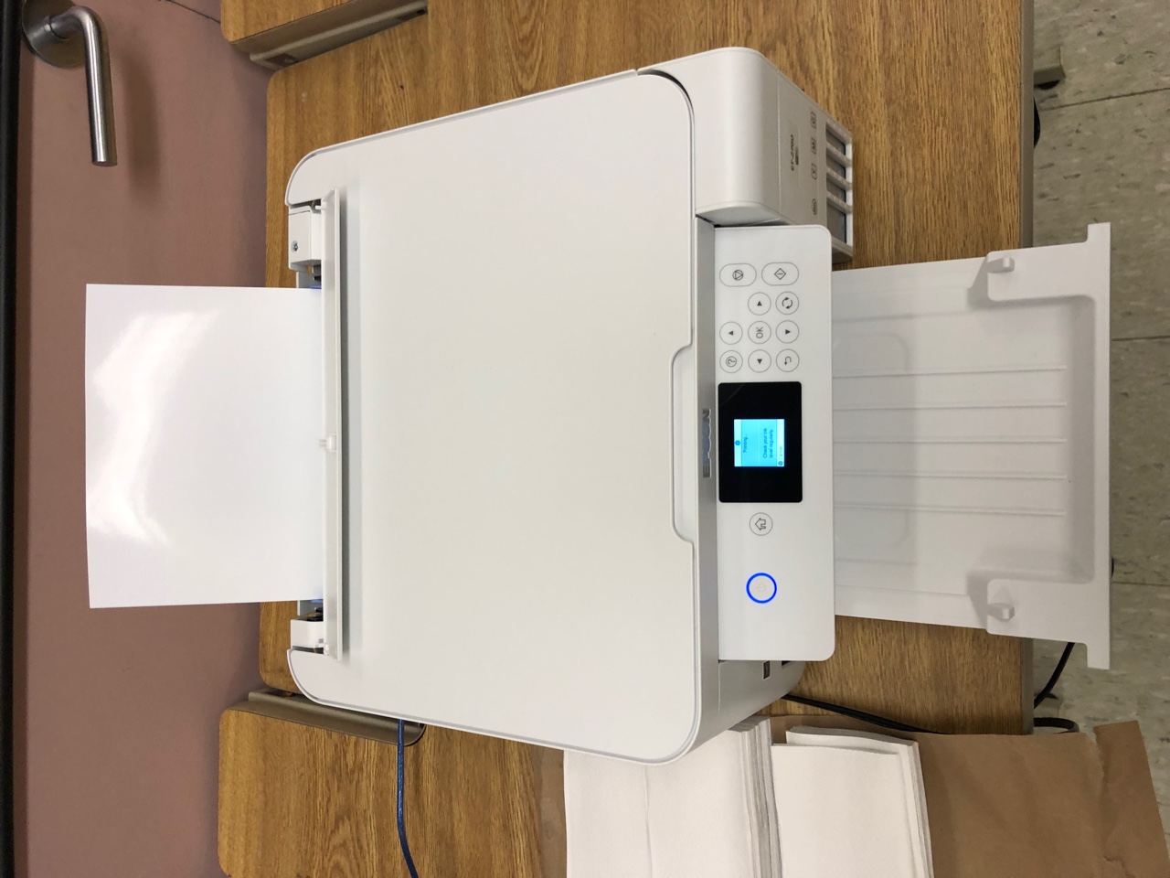
Open Circuit Design File: Let's start with printing the circuit design. Go to one of the Epson printers and open your circuit-design.pdf from your student google drive folder.
Insert Paper: Next, insert the paper. The paper has two sides, a glossy (shining) side and a non-glossy (matte) side. The glossy side should be facing up.
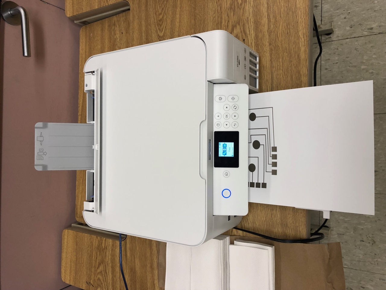
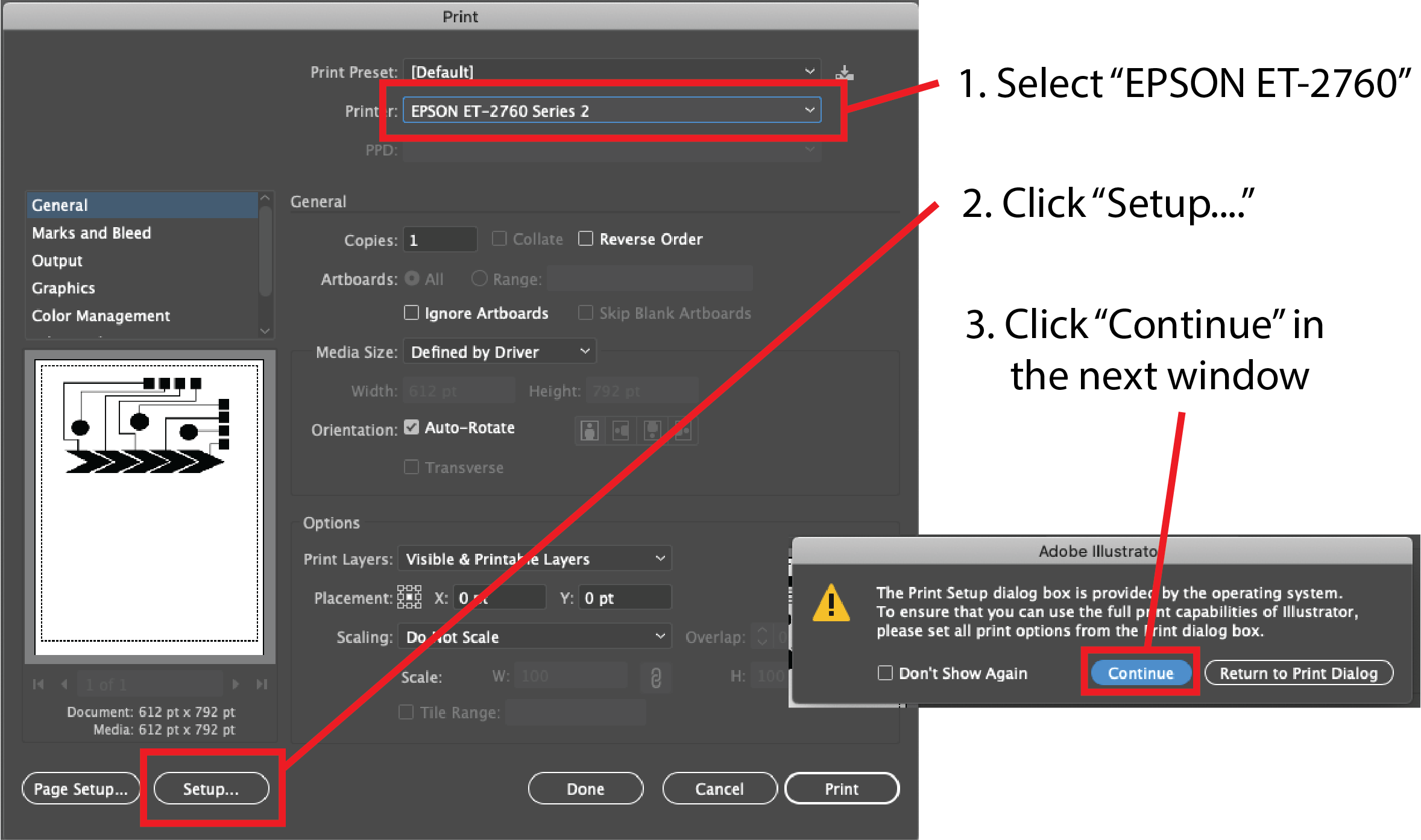
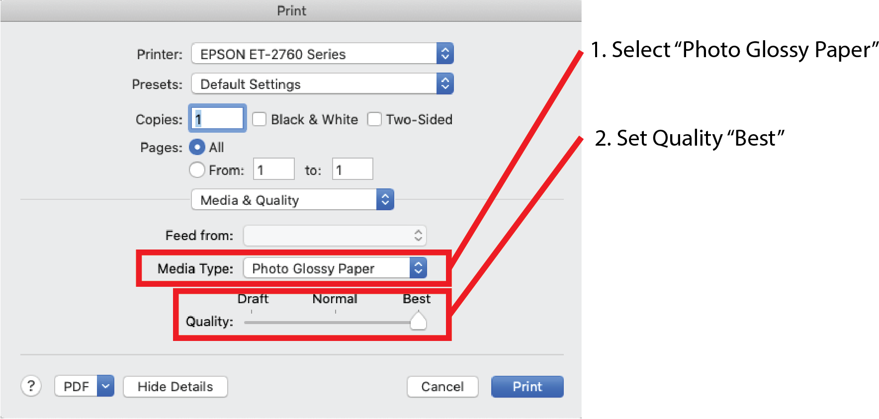
Set Printer Settings: Go to print, and from the 'Printer' dropdown select the Epson ET-2760. Next, click Setup (bottom left corner), then continue. Go to Quality and Media in the dropdown, then select Media Type and Photo Glossy Paper. Then go to Print Quality and drag the quality to the right most Best setting. Now you are ready to hit the print button.
Use Gloves to Handle Printed Circuit: Right after printing, the silver ink has not yet been fully cured, this takes a few hours. Therefore, you need to handle the printed circuit carefully as you could accidentially scrape off some silver with your fingers, especially if you have sweaty hands. Therefore, we ask you to handle the newly printed silver circuits with gloves on.
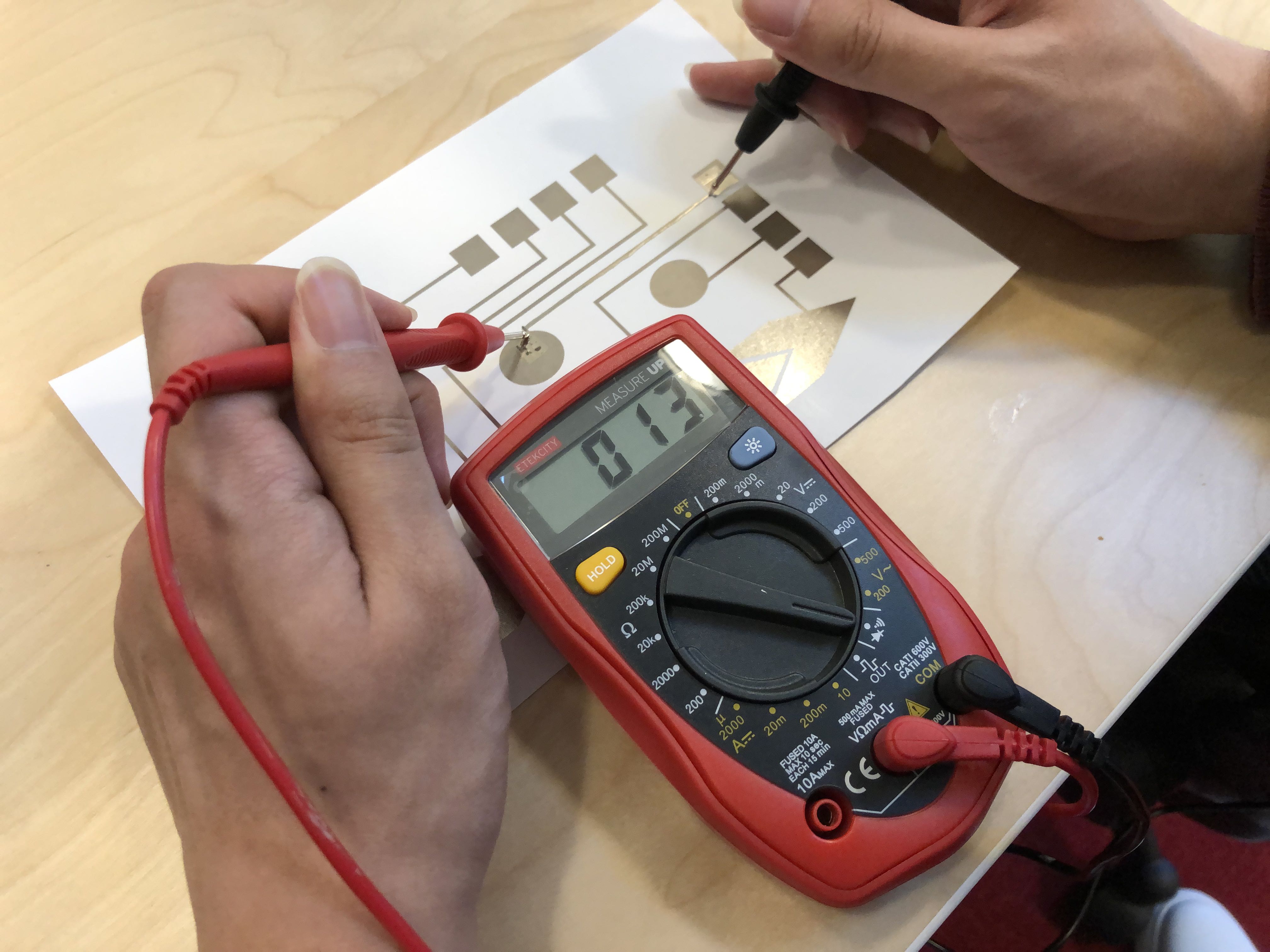
Check if your Print is Conductive: Before you print the color layer, let's first check if the silver layer is conductive or if anything went wrong during the print. Sometimes print nozzles clog and then some silver particles cannot exit through the nozzle, which leaves small gaps in your printed area, which reduces conductivity. The print is successful, i.e. highly conductive as indicated by a low resistance, if silver was deposited over the entire area. The print was unsuccessful if there are many tiny gaps, i.e. conductivity is low as indicated by a high resistance. To check the resistance, we can use a Digital multimeter (DMM).
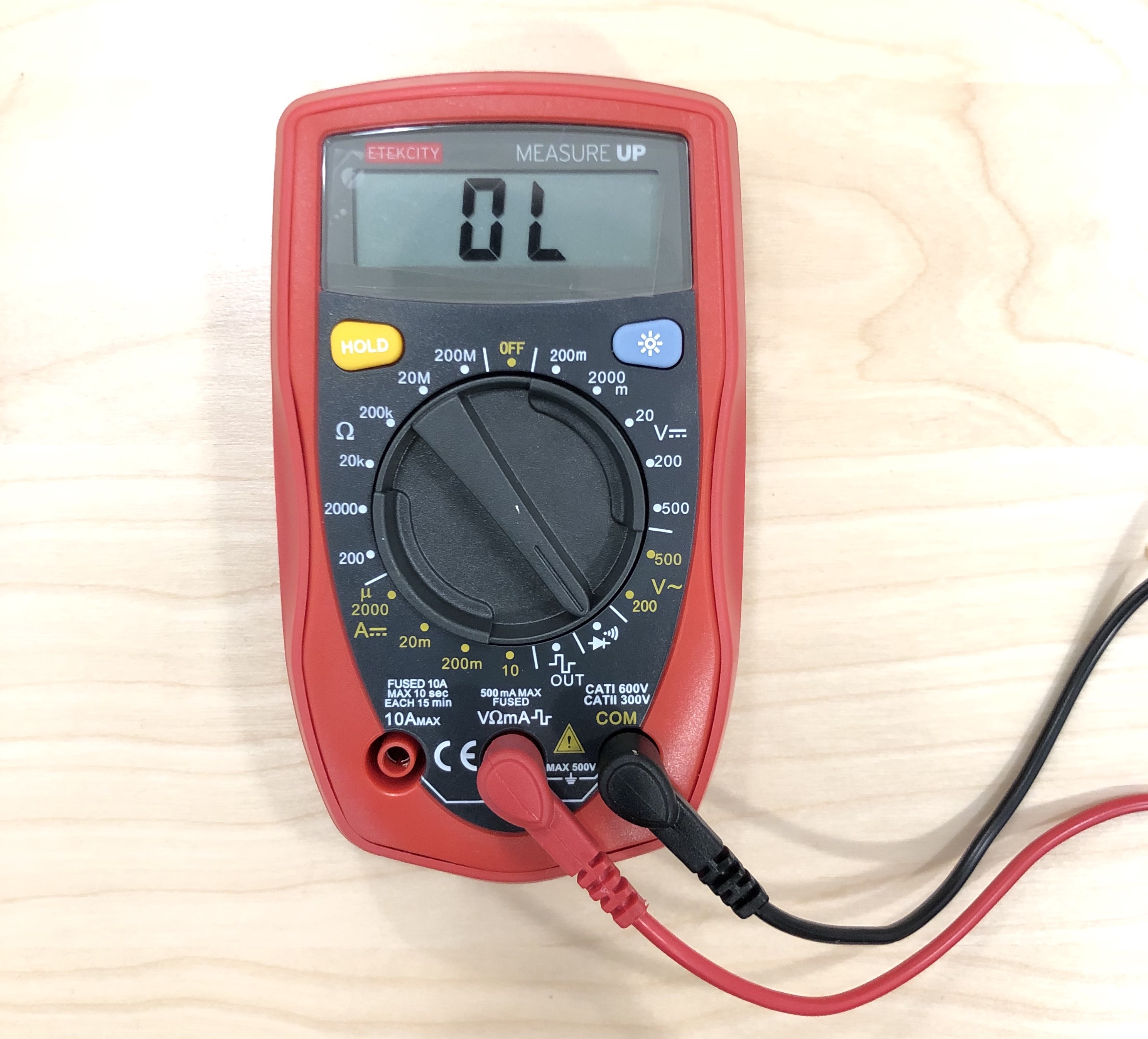
Using a Digital Multi-Meter to Check Resistance: Set the multimeter to Continuity mode. It may vary among DMMs, but look for a diode symbol with propagation waves around it (like sound coming from a speaker). Let's first check if the multimeter works at all. For this, touch the two probes together. The multimeter should emit a tone. This shows that a very small amount of current is flowing without resistance (or at least a very very small resistance) between probes, which is what we want. Next, hold the two measurement points at the beginning and end of a wire on your card to measure the resistance along the trace. Be careful with the probes since they are pointy and they may scratch off some silver. You should have a resistance of less than 300 ohms for your print. If you see a OL message in the display, your trace is broken and the resistance was so high it couldn't be displayed because it was out of range. If that happens to you, let us know and we will print your design again.
Installing the Silver Inkjet Printer Driver: For lab, we had you print from our shared computers since it is faster. If you want to print from your own computer in OH or during the group project, you can install the Epson EcoTank ET-2760 Printer Driver from here.
(7) Print the Visual Design
Let's print the visual design on the other side of the paper.
Ask somebody with a Mac to help you: The printer drivers for the color printers work well on Mac but unfortunately they don't work on windows. We only need the color printers today, so please ask somebody at your table who has a Mac to help you print your design.
Install the Color Printer Driver: Install the Canon MG2522/MG2525 CUPS Printer Driver (Mac) from here.
Open Visual Design File: Go to one of the Canon printers and open your visual-design.pdf from your student google drive folder.
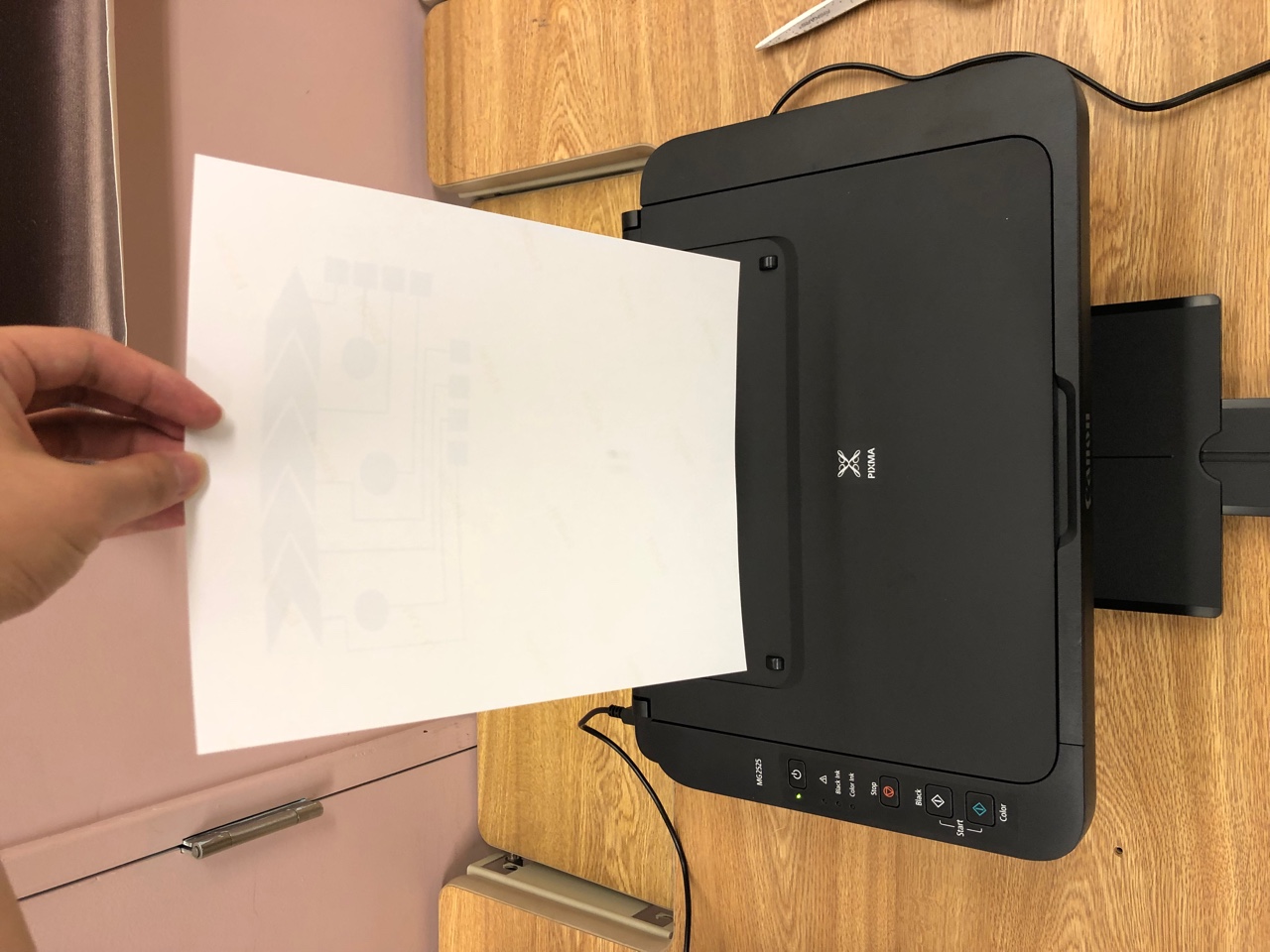
Flip Paper and Insert into Color Printer: We will print the music card design on the back side of the printed silver circuit. Make sure that you flip the photo paper so that the music card visual design and the circuit design matches up (see photos below).
Use the default printing settings.
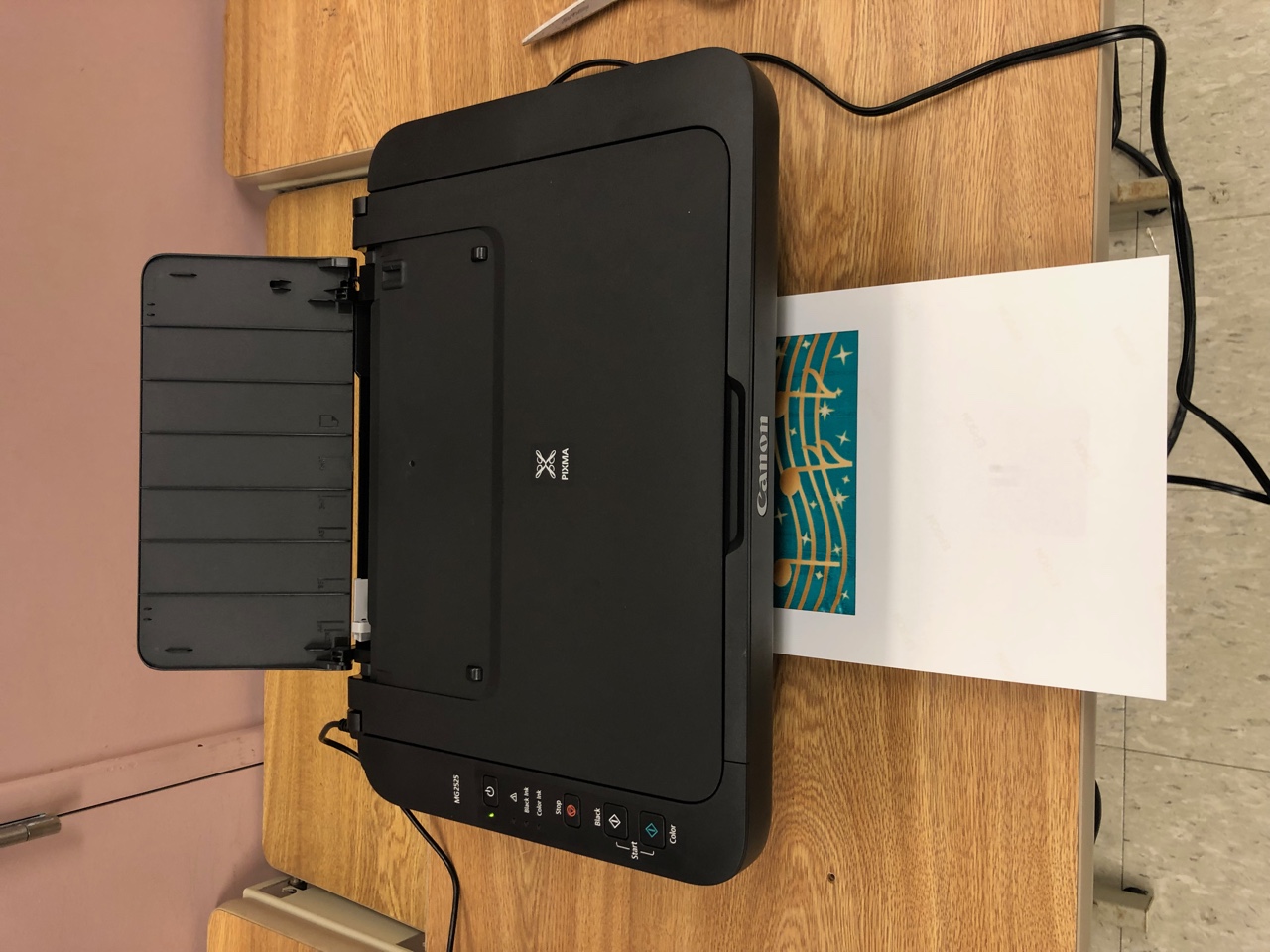
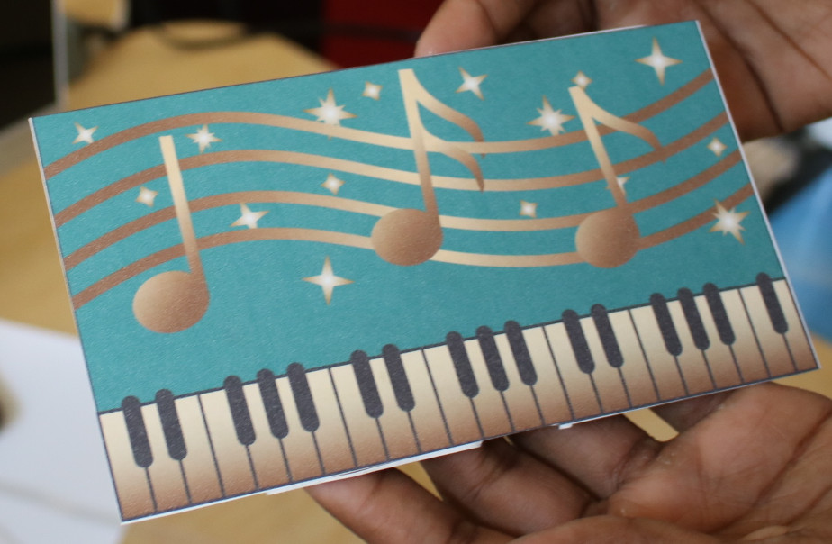
Once you have the visual design printed on the back side it should look like this.
(8) Laminate your Circuit Design
The last step for lab 1 is cutting the music card from the excess paper around it and finally laminating your card, so it is protected from any damage before you use it for the next labs.
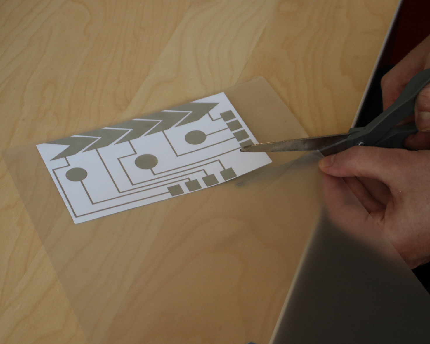
Cut the music card: Before you can start laminating the card, you have to cut it out. Use a scissor or rotary trimmer to do it.
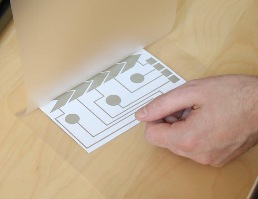
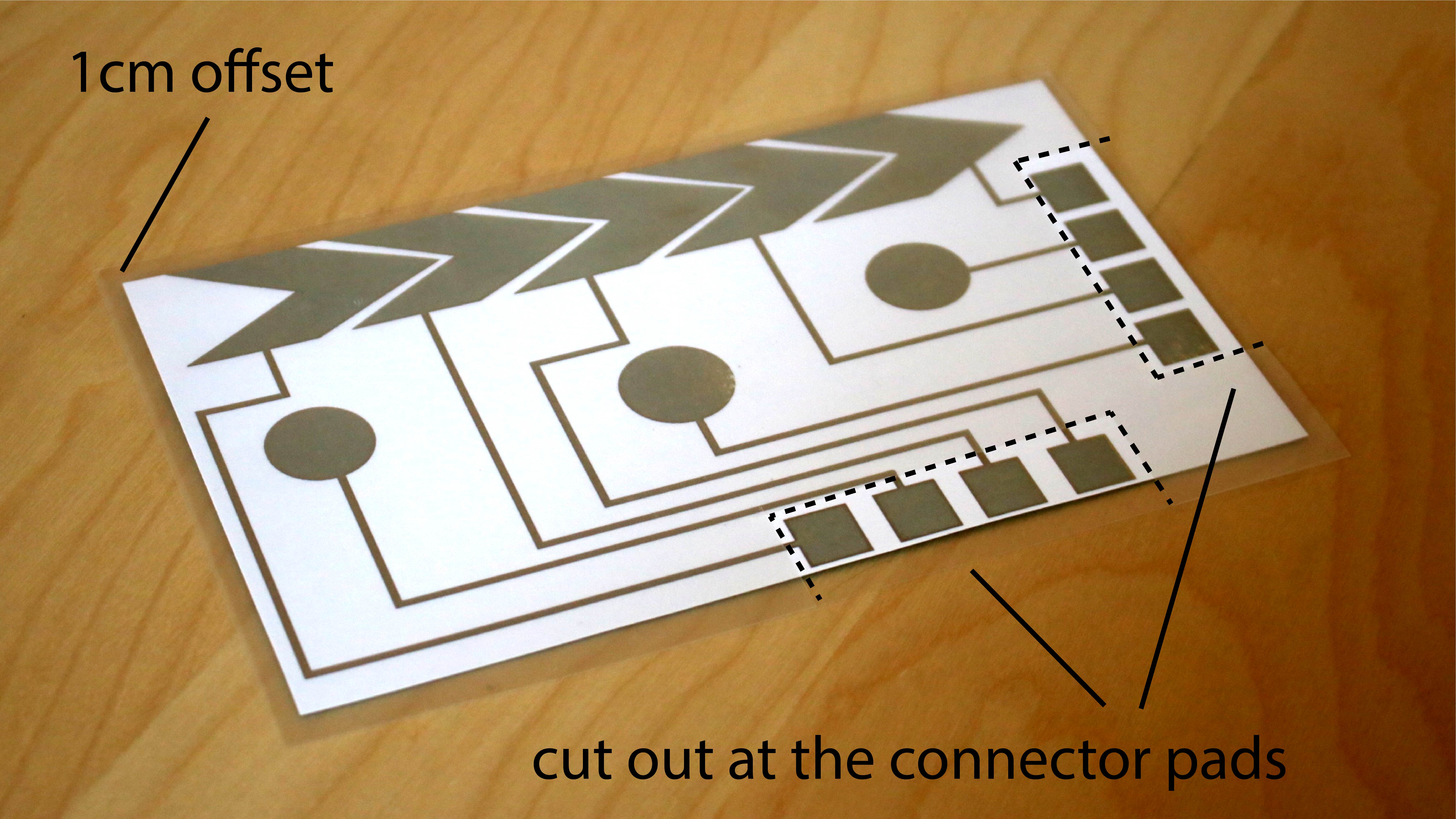
Cut the lamination sheet to be the size of the card: Before you can start laminating, you have to cut the lamination sheet to have the size of the music card. Lamination works by sandwiching the card design between two lamination sheets that are then fused together. Pick up a pair of lamination sheets (two transparent sheets that are glued together on one end) and put you music card between the two sheets. Push the card up to the side with the glued together edges. Next, with the card inside the lamination sheets, cut the lamination sheet along the edges of the music card while leaving 1-2cm space around the card. This frame will later glue together and hold the music card in place.
Cut out the holes for the connector pads: If you laminated the card as is, we would not be able to access the conductive silver of the connector pads anymore. Thus, you have to cut out a hole in the top lamination sheet for each connector pad. To do that, turn around the music card such that you can see the silver traces. Take a scissor and cut out a rectangle on the top lamination sheet where the connector pad is.
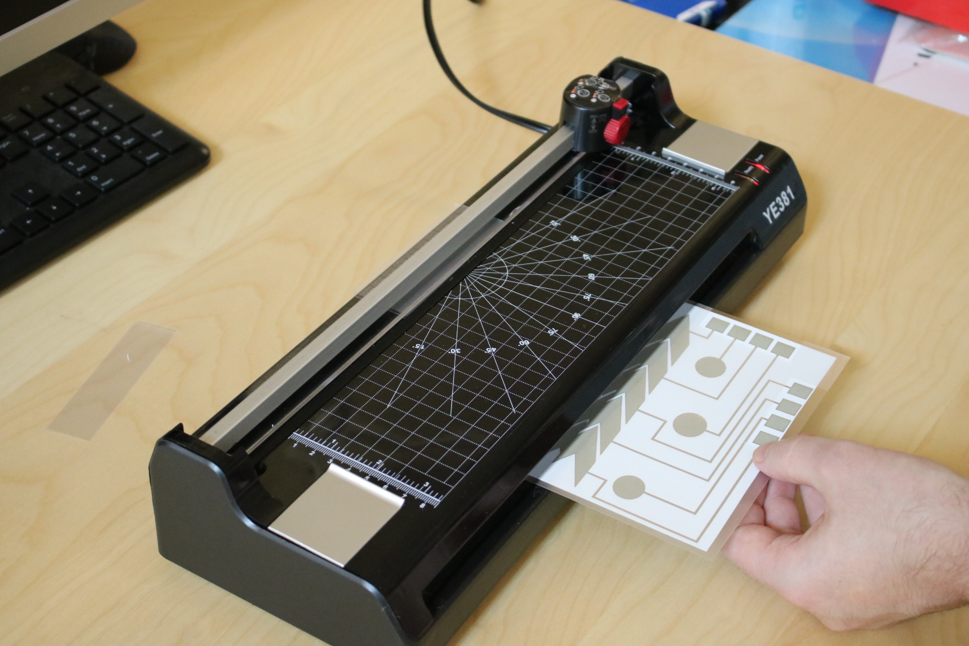
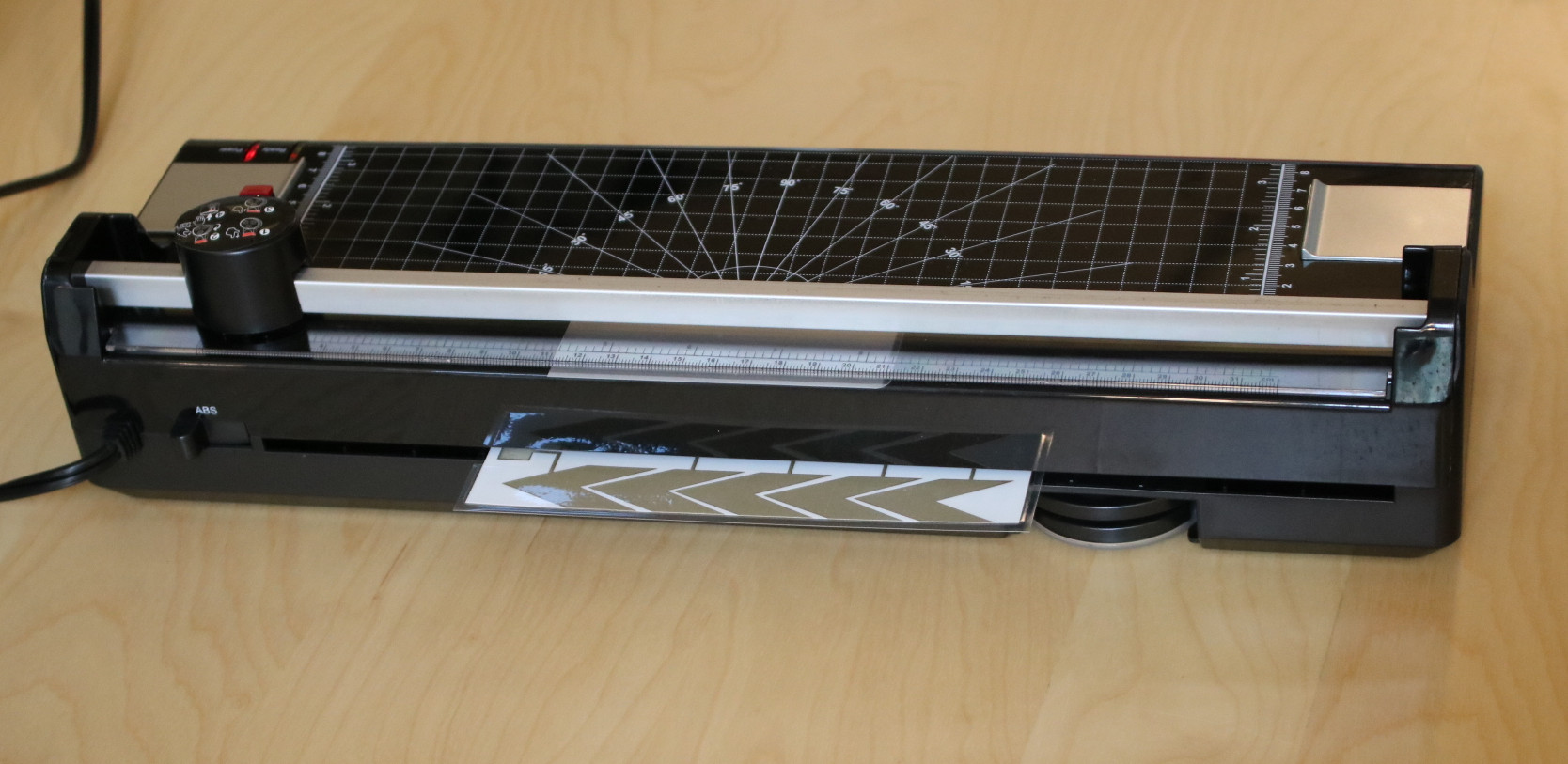
Laminate your card: Make sure that the laminator is turned on and set to hot lamination. If it is not warm, ask a TA for help.
Slide your music card into the front of the laminator. At some point you should feel that the machine starts to pull the card in. Now, you only have to wait for a few seconds. When the lamination is done, you can pull out you card from the back of the laminator.
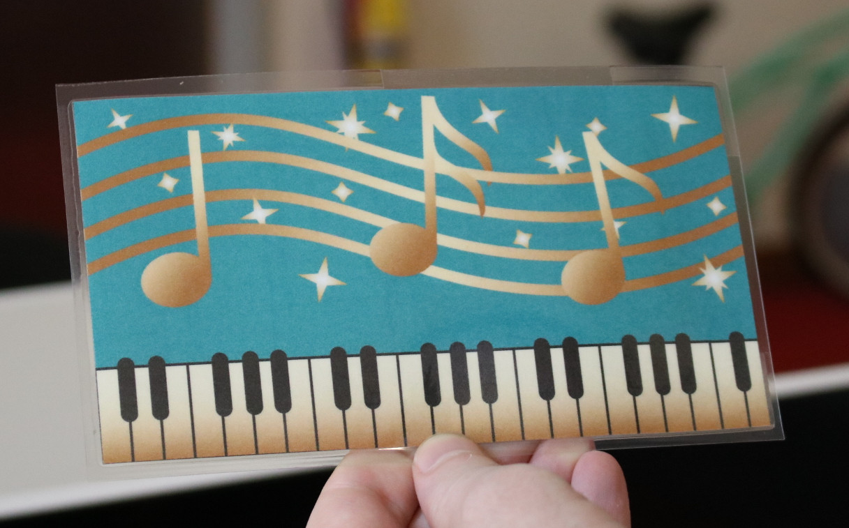
Your end result should look like this:
Deliverables:
At the end of the lab, upload to your student google drive:
- the Adobe Illustrator drawing file (.pdf) that contains both your circuit and your visual design on two separate layers
- the two individual pdfs (circuit_design.pdf and visual_design.pdf) you used for printing
- two photos showing the front and back of your inkjet printed card
What's next?: If you have time left, we recommend you either (1) do the safety trainings that were listed at the beginning of the lab, or (2) go to Lab 2 and start installing Arduino, the ESP core etc. and pick up your hardware bag from the teaching team (please only do this if you are confident you will stay in the class), or (3) create your laser cut business card homework.
Please let us know if you had any trouble with the fabrication devices or if anything was confusing in the write up.
You can add your comments here.