6.810 Engineering Interactive Technologies (fall 2021)
Lab 2: Sensing Touch from Inkjet Printed Circuit
In this lab, you will wire up your silver inkjet printed music card to a microcontroller and then write code to sense when the user touches one of the buttons.
Steps:
- Pick-up Hardware Bag
- Install Arduino and ESP Microcontroller Drivers
- Mount Microcontroller Onto Breadboard
- Build Capacitive Touch Sensing Circuit
- Install Arduino Capacitive Sensing Library
- Run Sample Code to Test if Touch Sensing Circuit Works
- Extend Circuit and Code to 3x Touch Sensors
- Threshold Touch Signals: Touched or not Touched?
- Format Serial Output
Deliverables
At the end of the lab, upload to your student google drive:
- a photo of your wired up music card connected to the breadboard and ESP microcontroller
- the Arduino code you wrote for touch sensing and Serial Communication (.ino file format)
- a short video showing your Serial Plotter output (the colored lines) of touching each touch button (.mov or .mp4, no more than 20MB)
Help us Improve Class Materials for Lab2:
Please let us know if you had any trouble with the circuit or programming or if anything was confusing in the write up.
You can add your comments here.
Before you start
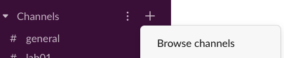
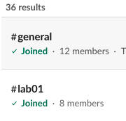
Join Slack Channels for 'Lab02' and your table number, e.g. 'Table5': Similar to last lab, please join the lab's slack channel and the channel with the table number you are sitting at.
 Create a Slide to Introduce Yourself: Consider taking a break some time during the lab to create your intro slide in this slide deck here.
EECS Safety Acknowledgement Form: If you haven't done it yet, read the EECS electrical safety form and then sign at the bottom. You need to do it before you start wiring up electronics today.
EECS Safety Training on ATLAS: If you haven't done it yet, do the ATLAS EECS safety training. You need to do it before you start wiring up electronics today. To find the training, go to ATLAS, then click 'Home' and in the sidebar 'Full Menu'. In the search bar, type in 'Learning Center' and select it. On the new page, click on 'Course catalog' and search for 'EHS00509w'. Then select the 'Web-based' version.
Create a Slide to Introduce Yourself: Consider taking a break some time during the lab to create your intro slide in this slide deck here.
EECS Safety Acknowledgement Form: If you haven't done it yet, read the EECS electrical safety form and then sign at the bottom. You need to do it before you start wiring up electronics today.
EECS Safety Training on ATLAS: If you haven't done it yet, do the ATLAS EECS safety training. You need to do it before you start wiring up electronics today. To find the training, go to ATLAS, then click 'Home' and in the sidebar 'Full Menu'. In the search bar, type in 'Learning Center' and select it. On the new page, click on 'Course catalog' and search for 'EHS00509w'. Then select the 'Web-based' version.
 Let's get started with the lab.
(1) Pick-up Hardware Bag
Ask a TA or LA to give you one of the hardware bags.
(2) Install Arduino IDE and ESP Microcontroller Drivers
Follow the instructions here to install the Arduino IDE, the ESP Core Board Manager, and the USB cable driver. If you already have any of those installed but you installed them more than 3 months ago, we still recommend you reinstall everything to make sure you have the latest version. Once you have the Blink program working, you are ready to go!
(3) Mount Microcontroller Onto Breadboard
Use only two breadboards for the labs: In total, you have four breadboards. However, only two breadboards should be used for the labs and the other two should be reserved for the problem set circuit.
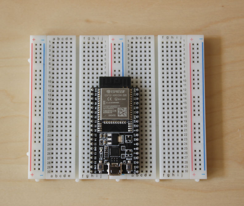
The ESP32 microcontroller is too large to be mounted on a single breadboard while still having access to all pins. Thus, you will put two breadboards next to each other and mount the ESP32 right in the middle between the two (similar to how you did it in 6.08).
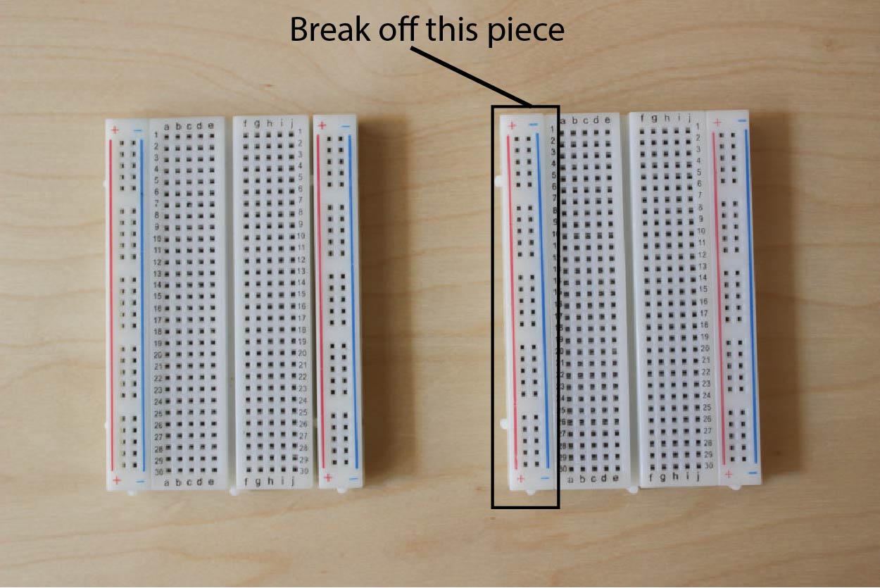
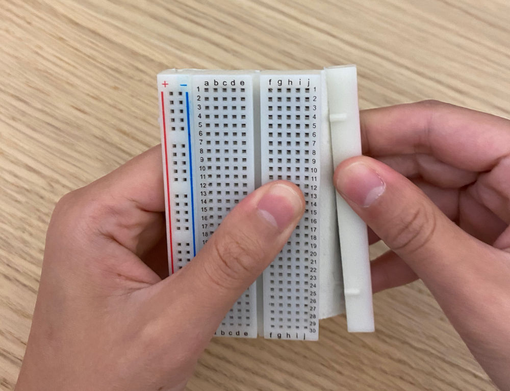
Assembling the Breadboards: Let's get started by placing the breadboards side by side. To be able to connect two breadboards together, we need to break off the power lane on one(!) breadboard on one(!) side (*not* both) (see image below).
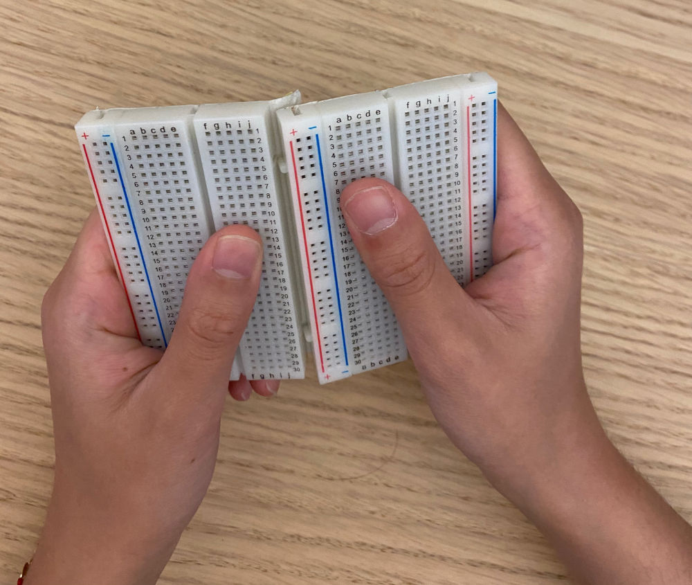
Connect Both Breadboards: Next, connect the two breadboard using the small pins on their sides.
Mount ESP onto Breadboards: Finally, put your ESP32 right onto the middle between the two breadboards
(4) Build Sensing Circuit on the Breadboard
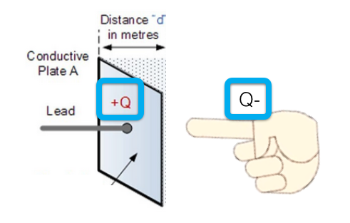
Capacitive Touch Sensing: We will implement touch sensing based on the principle of capacitive touch sensing. The circuit for capacitive touch sensing requires a sender pin, which outputs a signal, and a receiver pin, which listens to the signal. The sender and receiver pin have the touch button connected between them. When a user touches the touch button, the signal that was injected through the sender pin will take longer to discharge due to a capacitive object (finger) nearby. The microcontroller can measure this time difference and thereby detect touch.
Using Larger Resistors to Increase Sensitivity: To delay the discharge from the user's finger and make the time difference measurable on the ESP32, you will add a resistor between the sender and the receiver pin. A higher resistance enables more sensitive sensing (a 10MOhm resistor enables sensing of a finger up to 10cm distance, while a 10kOhm resistor would not make such a large distance detectable). However, higher resistance comes at the cost of speed because the signal takes longer to discharge. Since we only want to sense touch and do not need to sense hovering of a finger, we will use a 100kOhm resistor because it offers a good trade-off between sensitivity and sensing speed.
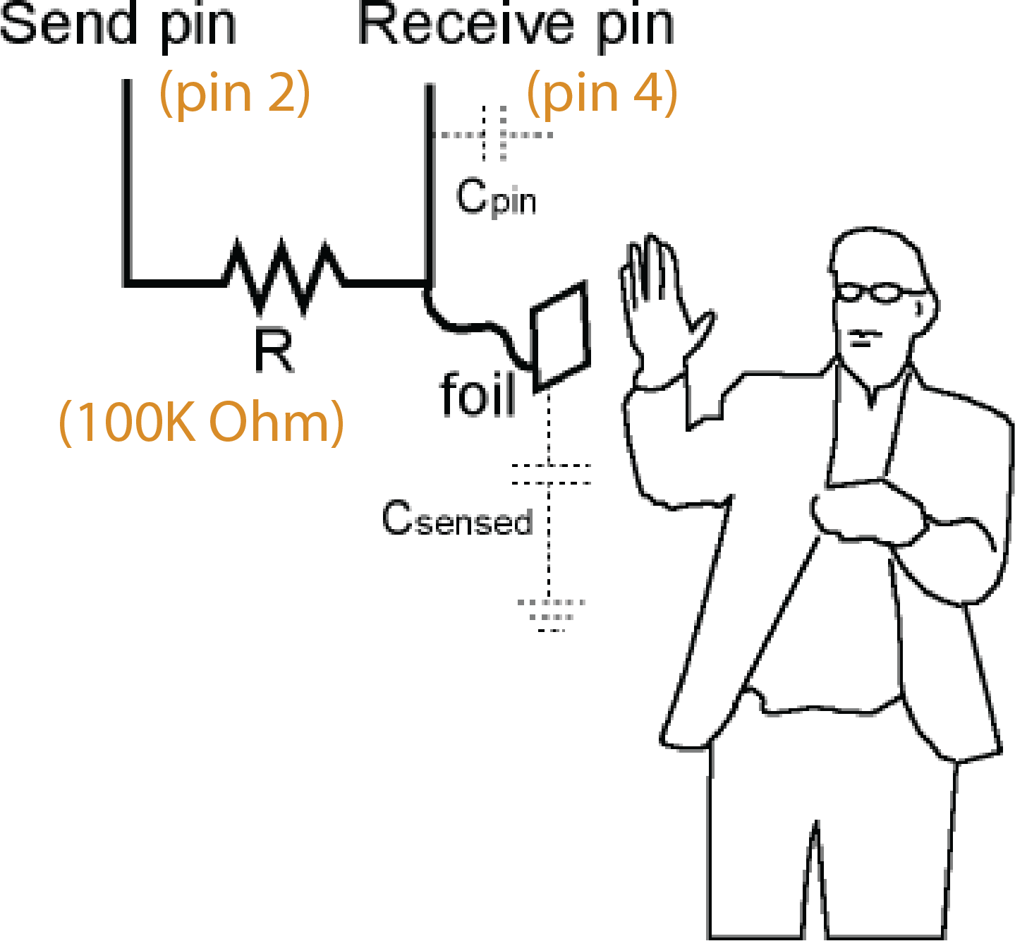
Let's build the circuit and write the code for one touch button, and then later repeat the procedure for the other touch buttons. To get started, look at the schematic and follow these steps:
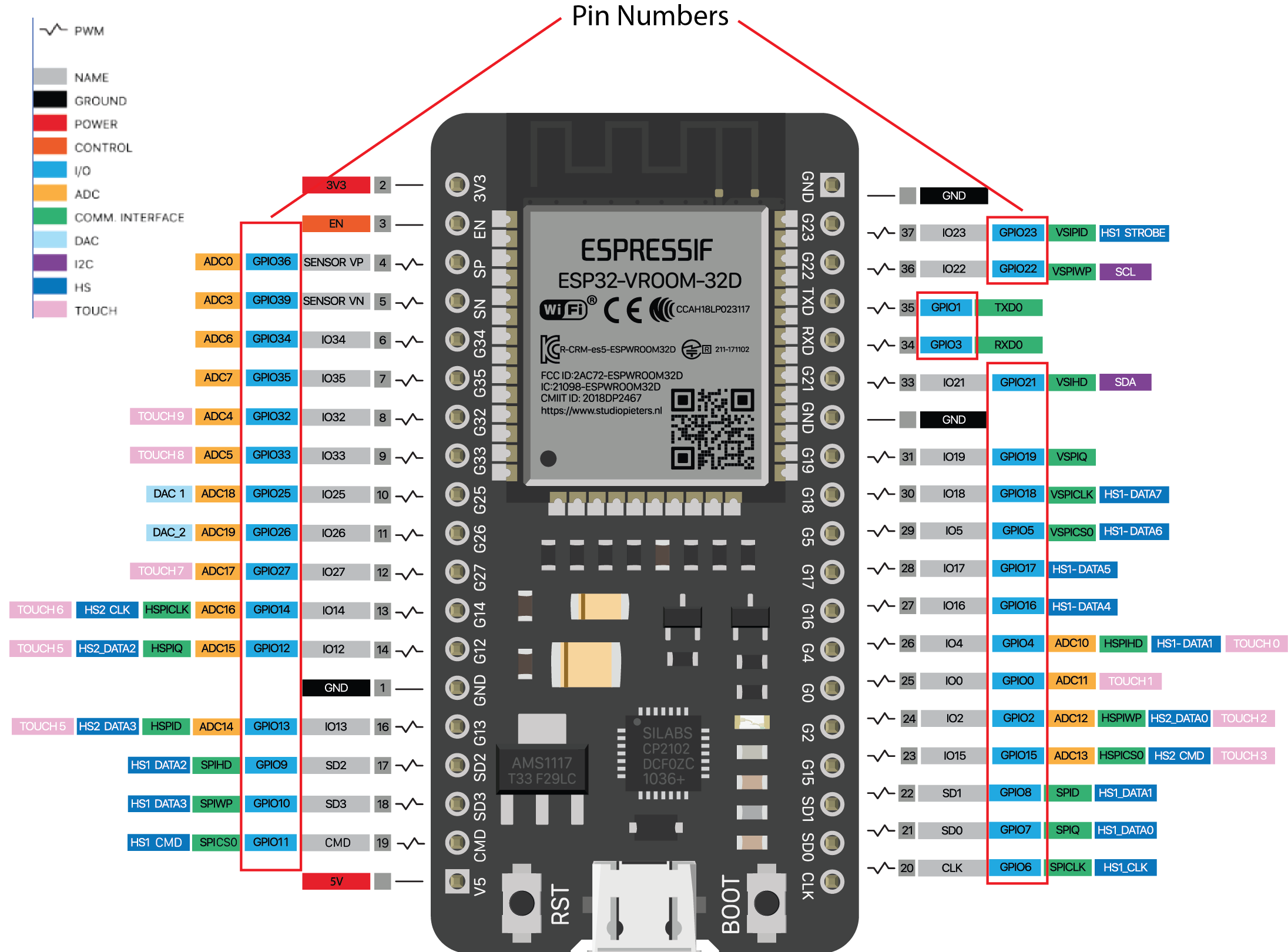
Sender Pin: For the sender pin, you can use any GPIO pin on the ESP. For this first touch button, we ask you to use GPIO pin 25.
Receiver Pin: For the receiver pin, it is best to use a pin that is labeled TOUCH (see ESP pin out below). These pins are optimized to serve as receivers for capacitive sensing and therefore return cleaner signals, so we will use them for our sensing application. For this first touch button, we ask you to use GPIO pin 14. *Never* use TOUCH0, it does not work on this particular model of ESP32.
Resistor: We will use a 100k Ohm resistor. Add the resistor to the circuit between your sender and receiver pin for your first touch button as shown in the schematic image above.
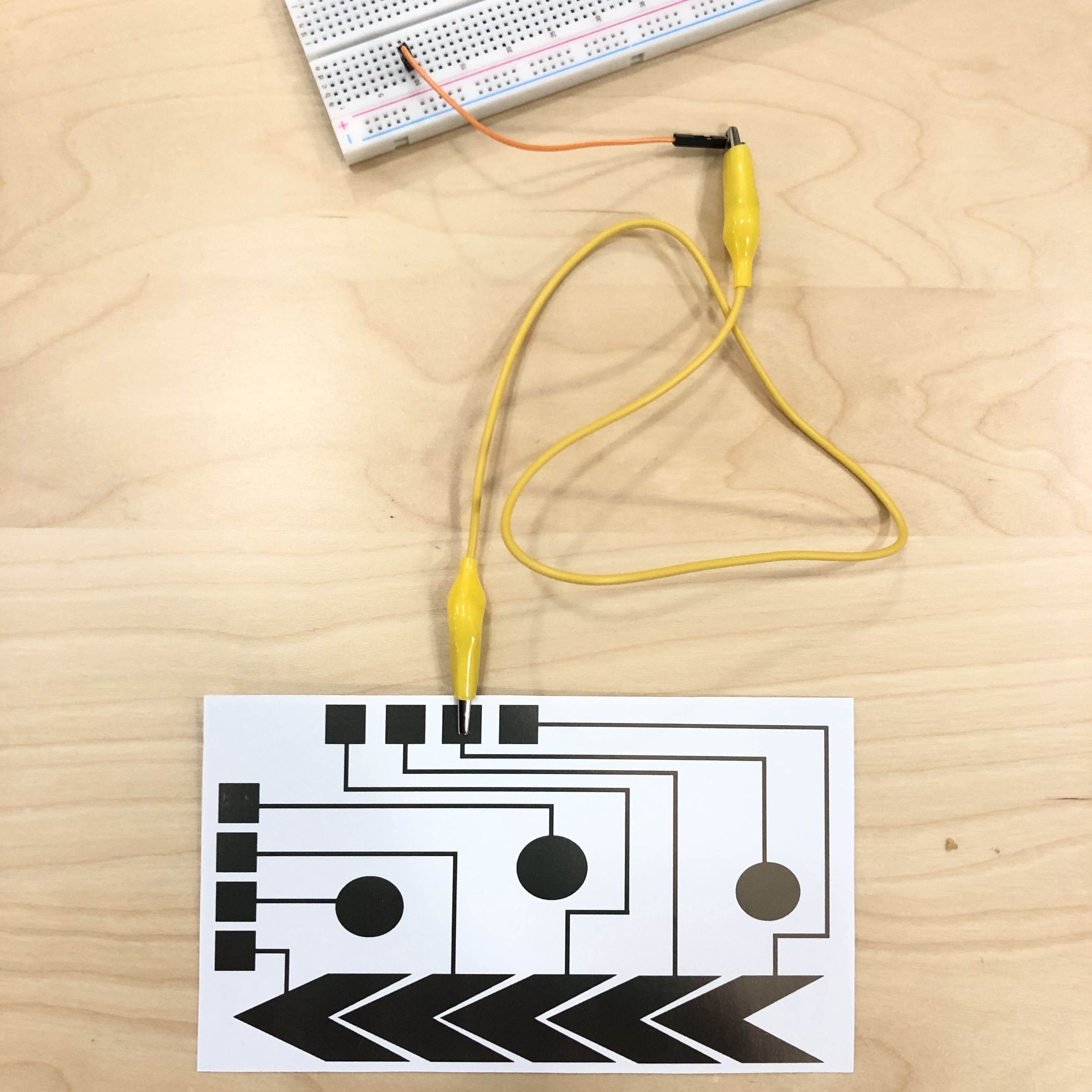
Connecting to the Inkjet Printed Touch Button: Finally, connect your printed touch button to the circuit on the breadboard. For this, you will use a crocodile clamp and a jumper wire. One side of the crocodile clamp goes onto the connector pad of the touch button, the other side clips into the end of a jumper wire. The jumper wire can then be used to connect to the breadboard. Once you have your first touch button wired up, you are ready to write the code for sensing touch with it.
Protecting the Silver Inkjet Printed Areas: Once you have the crocodile clamps connected, try to not move them around too much. The silver is pretty fragile and the crocodile clamp may scratch off more silver when it is jiggling around. Also when you pack up your card after class today, please be careful when removing your crocodile clamps from the silver areas.
(5) Install Arduino Capacitive Sensing Library
Next, we will write a program that receives the touch sensor signal from your first touch button and plots it on your computer. You can see the sample code that can do this below. To process the touch sensor signal, we will use the Arduino CapacitiveSensor library. You need to install this library before you can run the code.
We will install this library from Github instead of Aruidno Library Manager, since the ESP32 configuration is not in their official releases yet.
Install from github: First, if you accidentially installed the library already via Aruidno Library Manager, remove the previously installed library. You can delete it on Mac under Macintosh HD/Users/your-username/Documents/Arduino/libraries and on windows this is under My Documents\Arduino\libraries\. Once the library is deleted, go to the library's GitHub repository and download the master branch as a .zip file. Re-install the library via the .zip file by going to Sketch -> Include Library -> Add .ZIP Library. Don't forget to close the Arduino IDE and reopen it after install. Then try to compile the starter code one more time and see if it successfully uploads to your microcontroller.
/*******************************************************************************
* Capacitive Sensing for Touch and Proximity
*
* Prints the values of a capacitive sensor.
*
*******************************************************************************/
#include <CapacitiveSensor.h>

double analog_touch;

int sender = 25;

int touch_pin_1 = 14;

int samples_touch = 10;

CapacitiveSensor sensor1 = CapacitiveSensor(sender, touch_pin_1);

void setup()
{
   Serial.begin(9600);
}

void loop()
{

  // Send value 1
  analog_touch = sensor1.capacitiveSensor(samples_touch);
  Serial.println(analog_touch);


  delay(10);
}
(6) Run Sample Code to Test if Touch Sensing Circuit Works
Now that you uploaded the sample code to your microcontroller, let's use it to test if the touch sensing works.
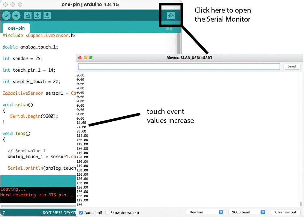
Use Serial Monitor to Observe Signal Changes During Touch: If you wired up your touch button according to our pin assignment, the code will write the touch signal to the serial monitor of the Arduino IDE. You can open the serial monitor by clicking on the squared icon in the upper right corder of your Arduino IDE window (see image below). Once you open the serial monitor, you should see a bunch of numbers fly by. If you touch your touch sensor, the values should change significantly. If your numbers don't change, there may be something wrong with your circuit. Double check your circuit and then ask a TA for help.
(7) Extend Circuit and Code to 3x Touch Sensors
In this lab, we will only build the circuit and write the code for the touch buttons. We will take care of the slider later.
Extend Circuit: Since you have three notes that serve as touch buttons, you need to extend your circuit to read those touch signals as well. When building the circuit for your other touch buttons, you can use the same sender pin for all three touch buttons. Only the receiver pin has to vary, i.e. you need one receiver pin for each touch signal you want to read. Also each touch sensor needs its own 100k Ohm resistor. The pin numbers are up to you. Remember to use a TOUCH pin for receiving.
Extend Code: Next, extend your code to read all 3 of your touch sensors. Plot the results in the format:
touchButtonValue1, touchButtonValue2, touchButtonValue3 \\end of line
You can create a string from multiple values by concatenating them with a '+' (string1+string2..). Don't forget the ',' character between the touch button values.
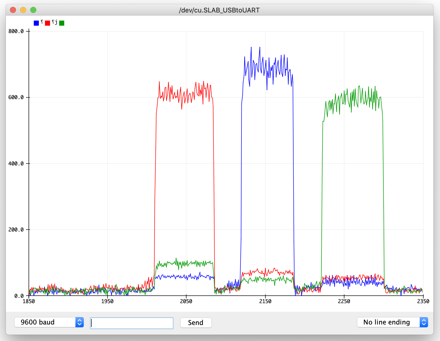
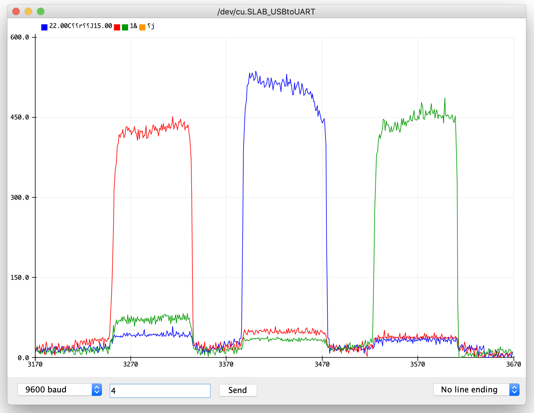
Test If Touch Buttons Work: Because of the formatting we used (Serial.print() values separated by commas), we can plot the received values in a nice graph. To do this, open the Serial plotter by clicking on Tools->Serial Plotter and you should see all three touch button variables plotted at the same time. Touch each touch button to see if the signal changes. If you see no changes, either your circuit or your code have a bug. Below you see how we touch the button 1 first, then button 2 and finally button 3. You can increase the number of times the signal is sampled by increasing the value of samples_touch in your code.
(8) Threshold Touch Signals: Touched or not Touched?
Next, we want to convert the raw signal into touch events, i.e. button touched or button not touched. As you saw in the serial plotter, the values for each sensor can vary pretty wildly for the reasons mentioned in lecture. We will do more filtering of signals later in class, but for now we will make a rough estimate in which range our sensor signal falls for each touch button.
Write Code to Determine Touched/NotTouched: Write code in the form of a simple if/else statement to determine if a touch button was touched or not. Look at the serial plotter to determine the range for each touch button. Note that the values may be different for each touch button because of inconsistencies in the print, slightly different sizes for each touch button etc.
Adjust the Loop() speed to Plot Every 200ms: Adjust the loop speed to output if a touch button was touched or not every 200ms. Remember from 6.08 that using delay() is not a good way to do this and doing this in a non-blocking way is much better.
(9) Format Serial Output
In the next lab, we will read the output from the Serial Monitor into a program called Processing. For this, we want to make sure our output is formatted well. Replace the old Serial.write() statements with the formatting below:
Formatting Output for each Sensor: For each individual touch button, we want to format our output so that:
(sensor ID),(is_touched);
(sensor ID): is either 0, 1 or 2 and corresponds to the ID of the touch button.
(is_touched): is either 0 or 1 (0 if the sensor is not touched, and 1 if it is touched).
A sample output for touching only sensor 0 should look like:
0,1;
1,0;
2,0;
Print Serial Messages only when Button State Changes: So far we have been printing all touch button values to the Serial monitor no matter if the state of the touch button changed or not. As the last step in this lab, you need to print new information only if the sensor state changes, i.e. a touch button was not touched before but is now being touched, or the touch button was touched but the user just released the finger. Change the code such that it tracks in which state each sensors is currently in. Check for a state change and send the Serial message only once.
Example:
If sensor 0 gets touched, this message is printed once:
0,1;
Then when the user lifts the finger again, this message is printed once:
0,0;
In between these two events, no message should be sent.
Deliverables
At the end of the lab, upload to your student google drive:
- a photo of your wired up music card connected to the breadboard and ESP microcontroller
- the Arduino code you wrote for touch sensing and Serial Communication (.ino file format)
- a short video showing your Serial Plotter output (the colored lines) of touching each touch button (.mov or .mp4, no more than 20MB)
What's next?: If you have time left, we recommend you either (1) create your intro slide here, or (2) create your laser cut business card, or (3) continue with lab 3.
Please let us know if you had any trouble with the circuit or programming or if anything was confusing in the write up.
You can add your comments here.
/*******************************************************************************
* Capacitive Sensing for Touch and Proximity
*
* Prints the values of a capacitive sensor.
*
*******************************************************************************/
#include <CapacitiveSensor.h>
double analog_touch;
int sender = 25;
int touch_pin_1 = 14;
int samples_touch = 10;
CapacitiveSensor sensor1 = CapacitiveSensor(sender, touch_pin_1);
void setup()
{
Serial.begin(9600);
}
void loop()
{
// Send value 1
analog_touch = sensor1.capacitiveSensor(samples_touch);
Serial.println(analog_touch);
delay(10);
}touch buttons. We will take care of the slider later.touchButtonValue1, touchButtonValue2, touchButtonValue3 \\end of line(sensor ID),(is_touched);0,1;
1,0;
2,0;
0,1;0,0;