DOI PDF Video Slides Videos
Press
- MIT MRL News
- MIT EECS News
- SciTech Daily
- 3D Printing Industry
- TechXplore
- Hackster.io
- 3DPrint.com
- Chronicle
- I-News
- TechiLive
- The Times of Truth
- 3S Computers
- News Update
- News Brig
- Newspot Nigeria
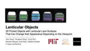


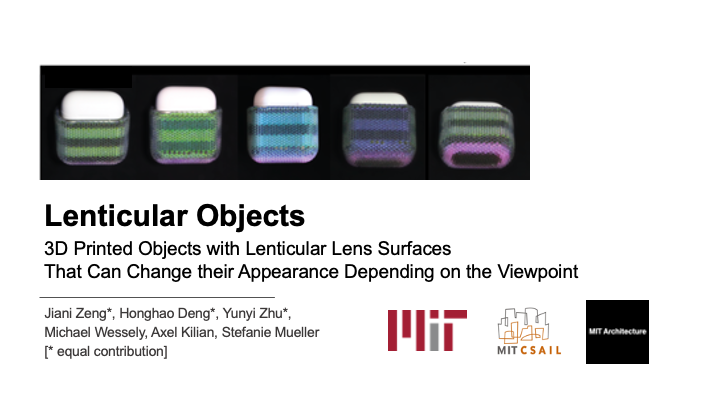


Lenticular Objects: 3D Printed Objects with Lenticular Lens Surfaces that Can Change their Appearance Depending on the Viewpoint
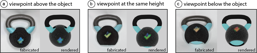
Figure 1: 3D printed objects with lenticular lens surfaces enable viewers to see different appearances from different viewpoints(a: looking down; b: looking horizontally; c: looking up). Our user interface supports designers in setting up different viewpoints and assigning the corresponding textures. On export, it automatically generates the files for fabrication. Designers can then 3D print the object geometry, lenses, and underlying color patterns in a single pass with a multi-material 3D printer.
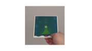
In this paper, we present a method that makes 3D objects appear differently under different viewpoints. We accomplish this by 3D printing lenticular lenses across the curved surface of objects. By calculating the lens distribution and the corresponding surface color patterns, we can determine which appearance is shown to the user at each viewpoint.
We built a 3D editor that takes as input the 3D model, and the visual appearances, i.e. images, to show at different viewpoints. Our3D editor then calculates the corresponding lens placements and underlying color pattern. On export, the user can use ray tracing to live preview the resulting appearance from each angle. The 3D model, color pattern, and lenses are then 3D printed in one pass on a multi-material 3D printer to create the final 3D object.
To determine the best fabrication parameters for 3D printing lenses, we printed lenses of different sizes and tested various post-processing techniques. To support a large number of different appearances, we compute the lens geometry that has the best trade-off between the number of viewpoints and the protrusion from the object geometry. Finally, we demonstrate our system in practice with a range of use cases for which we show the simulated and physical results side by side.
INTRODUCTION
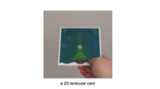
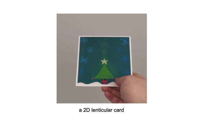
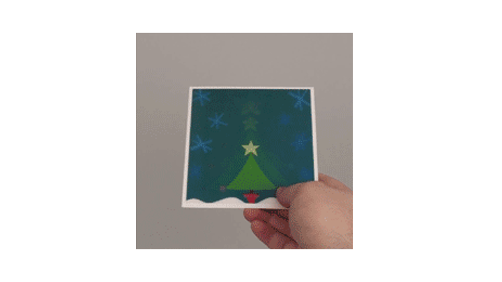
Lenticular printing refers to the method of using lenticular lenses to show different images from different viewpoints. It is commonly applied in advertisement and arts to achieve special purpose effects, such as showing various images on one commercial motion card or creating artistic effects with the illusion of depth.
Traditionally, lenticular prints are limited to 2D. They are fabricated by placing flat lenticular sheets onto 2D color patterns, which are composed of multiple images. Depending on the viewpoint, light rays enter the lens at different angles and thus reflect off different parts of the underlying color pattern. Therefore, under different viewpoints, a different part of the color pattern is visible to the viewer’s eye and as a result the viewer sees only a particular image that is contained in the color pattern.
One reason why lenticular prints do not yet exist in the form of 3D objects is that up until recently, no fabrication process existed that was able to manufacture the lenticular lenses and high resolution color patterns on doubly curved surfaces. However, over the last years, multi-material 3D printers have been developed that can print with a multitude of materials and in high-resolution color. For example, the 3D printer Stratasys J55 can print with optical clear materials, which can be used for the lenses, as well as CMYKmaterials, which can be used to print the color pattern.
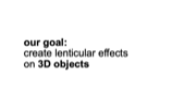
In this paper, we explore how to leverage the recent advances in multi-material 3D printing to create curved 3D objects with lenticular surfaces. To facilitate the creation of objects that look different from different viewpoints, we provide designers with a3D editor that takes as input the 3D model, the desired viewpoints,and the corresponding images and then computes the lens placement and color pattern across the object’s surface (Figure 1). Before fabrication, designers can preview the resulting object from each viewpoint via ray tracing, and then send it to the 3D printer.
To determine the best fabrication parameters for 3D printing lenses, we printed different lens sizes (2mm-5mm) and tested different post-processing techniques (different types of varnishes and oil). To achieve a large number of different appearances on one3D object, we computed the lens geometry that has the best trade-off between a large number of viewpoints and avoiding protrusion of the lenses from the object geometry. We show that although our system can support up to 19 different appearances per object as shown by our digital ray tracing simulation, inaccuracies in current fabrication techniques do not yet allow for these results in practice. We demonstrate the usefulness of lenticular objects with 4 application examples in product design and HCI showing the simulated and the physical results side by side.
In summary, we contribute:
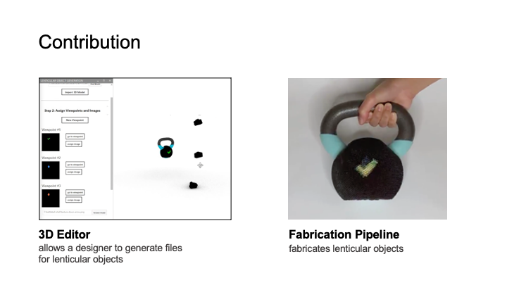
- an end-to-end fabrication pipeline for printing lenticular objects in a single pass on a multi-material 3D printer by print-ing lenticular lenses and color patterns on doubly-curved object geometries;
- an interactive 3D editor plug-in that allows designers to define multiple viewpoints and assign the corresponding textures and that generates the resulting fabrication files;
- four application scenarios that demonstrate lenticular objects made with our fabrication pipeline.
BACKGROUND: LENTICULAR DISPLAYS
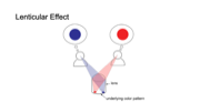
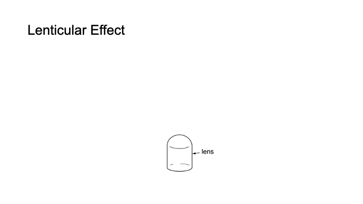
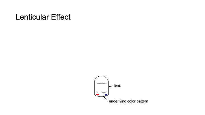
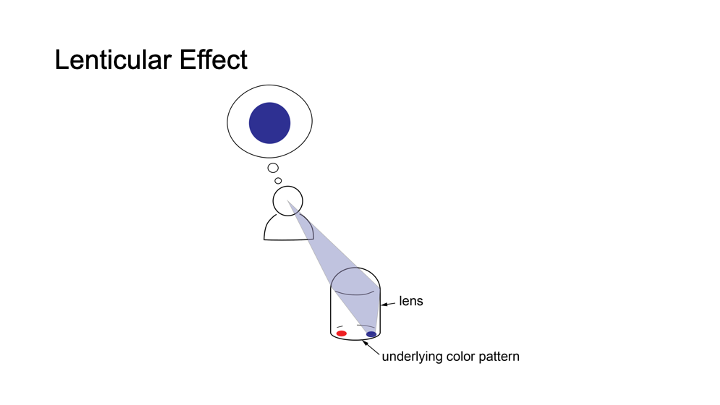
Figure 2 shows a simplified illustration of a lenticular lens that displays a different appearance under each viewpoint. To create this effect, the lens has a color pattern consisting of multiple colored image spots underneath. Because of the magnifying effect of the lens, it displays the color from only one of the colored image spots, which is only a small portion of the entire area under the lens (Figure 2a). Because each lens only shows one image spot from each viewpoint, the colored image spot is the equivalent to one pixel in a display. Which image spot the viewer sees and thus which color the ’pixel’ has, depends on the viewpoint of the viewer due to the different incident angles of the light hitting the lens (Figure 2b). Since each lens represents one pixel in the display, multiple lenses together form a lenticular display and collectively show an image that varies dependent on the viewpoint.
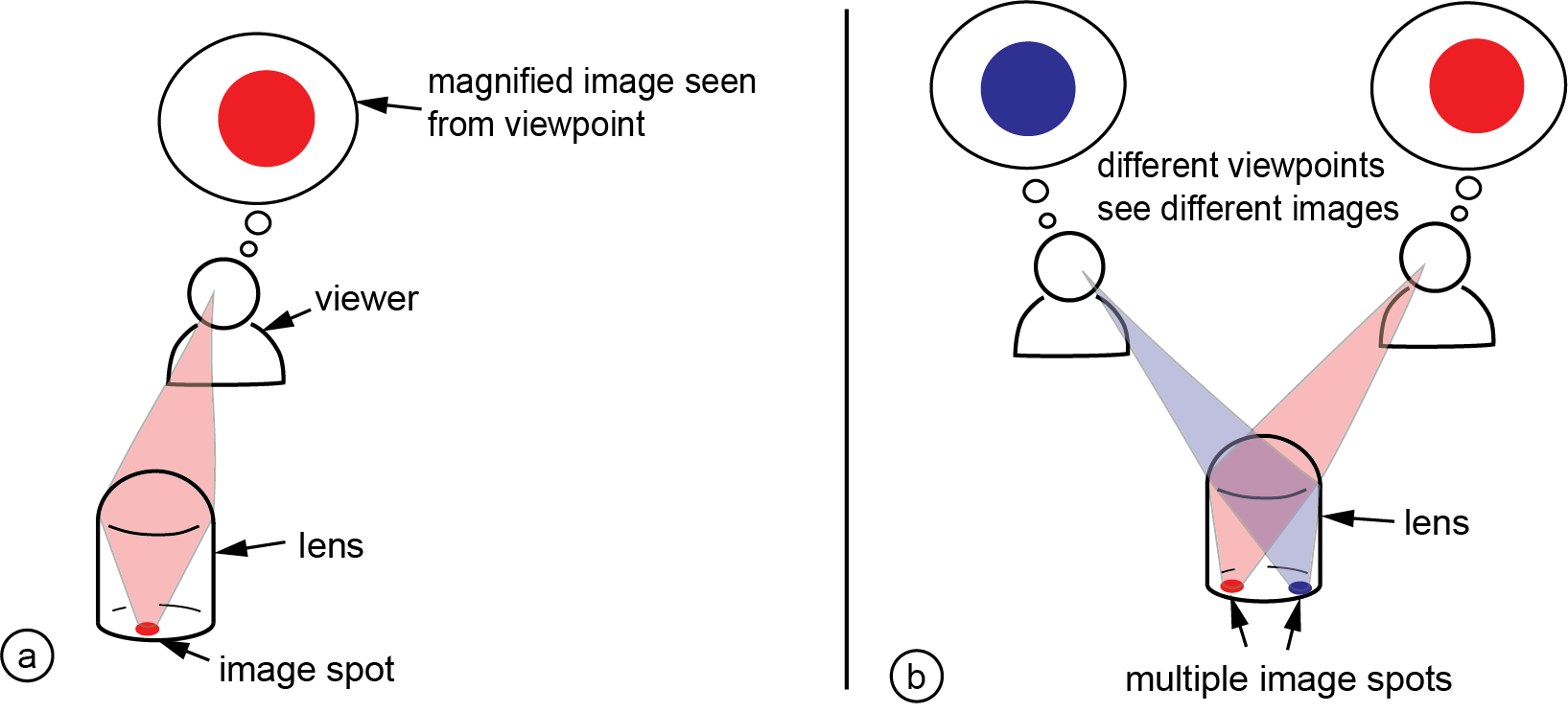
Figure 2: (a) Magnifying effect of a lens: from each viewpoint, the user sees only a small fraction of the underlying color pattern, i.e. one image spot. (b) From different viewpoints, users see different image spots under the lens, thus from each viewpoint the lens shows a different color.
The quality of a lenticular display is determined by the size of the lenses and the number of image spots that fit under a lens. The smaller the lens, the smaller each pixel is, and thus the more pixel scan fit in a given area, resulting in a higher resolution of the image.The number of image spots that fit under a lens determines how many different colors a pixel can take on, and thereby determine show many images the viewer can see from the overall display.We show later in our paper how we compute the lens geometry that has the best trade-off between the number of viewpoints (i.e.image spots underneath the lens) and the protrusion from the object geometry. In addition, we will report the results from experiments,in which we investigated the trade-off between the size and the resulting quality of a lens. Before reporting on these experiments,we will illustrate in the next section how to create 3D printed objects with lenticular surfaces with our custom design tool.
DESIGN TOOL FOR 3D LENTICULAR DISPLAYS
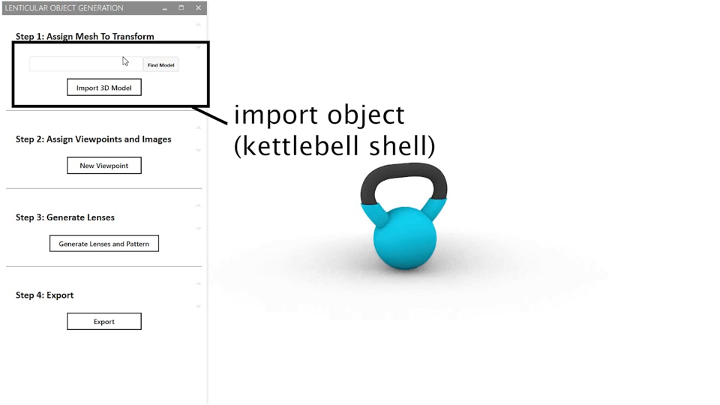
To support designers in creating 3D lenticular displays, we developed a design tool that is integrated into an existing 3D modeling environment, Rhino3D (open source code available here: link). Designers start by loading the 3D model of the object and then defining a set of viewpoints and correspond-ing visual appearances. Our editor then automatically places the lenses on the 3D geometry and assigns the corresponding color pattern to each lens. Before fabrication, designers can preview the resulting object via ray tracing. On export, our tool provides a set of fabrication files ready for 3D printing.
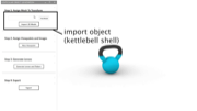
In the next section, we demonstrate the functionality of our editor at the example of a kettlebell that guides the user into the correct exercise pose, i.e. shows a check mark when the user holds the kettlebell at the correct height, and an upward and downward arrow when the kettlebell is being held too low or too high (Figure 1).
Defining Viewpoints by Placing Virtual Cameras
After loading the 3D model of the object, designers define the viewpoints by placing virtual cameras in the viewport at the desired3D positions (Figure 3a). To do this, designers first click the ’new viewpoint’ button, which creates a virtual camera in the viewport. It also adds the viewpoint to the list of all viewpoints in the panel.Designers can then either move the camera in the viewport or alternatively enter a 3D coordinate to position it. While the designer is moving the camera, our editor automatically orients the camera to always face towards the object. Designers can verify that theviewpoint is correctly positioned by clicking ’go to viewpoint’ in the panel, which shows the view from the selected virtual camera to the object.
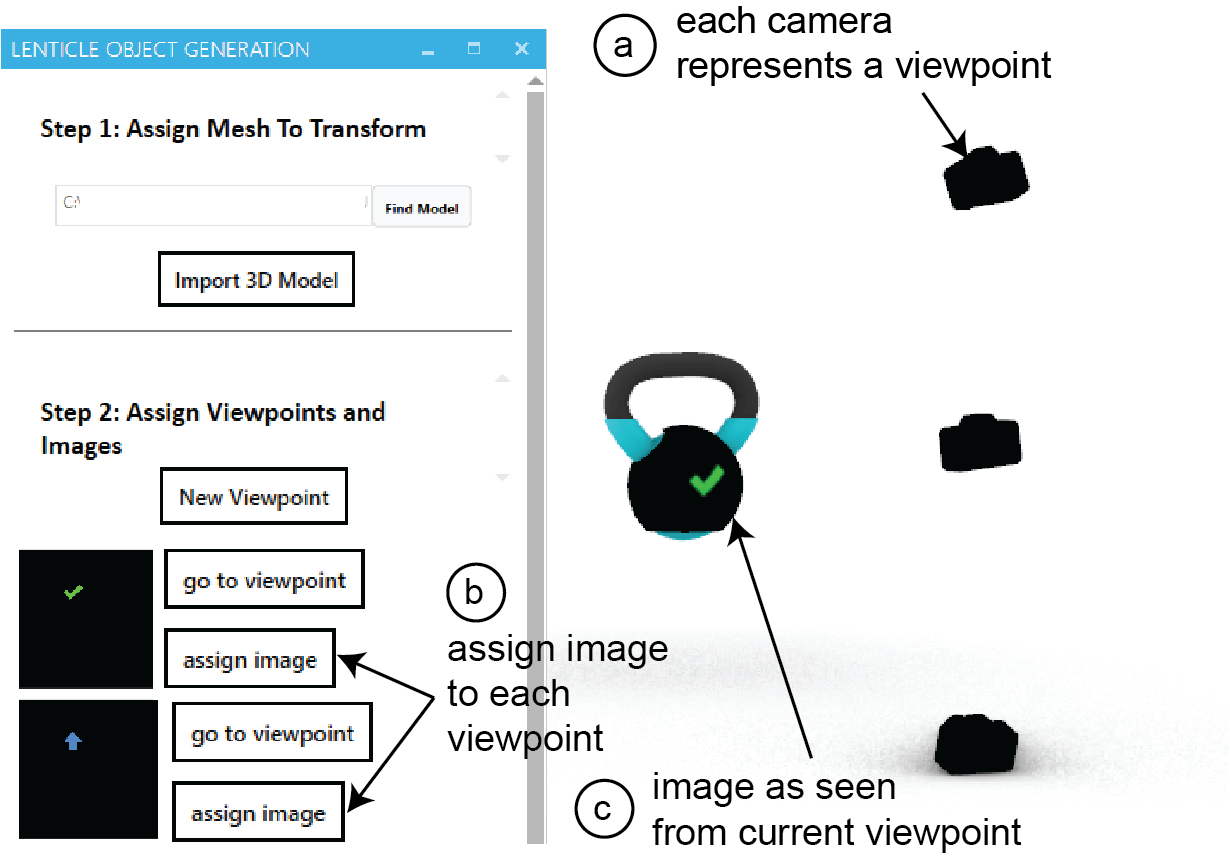
Figure 3: Defining Viewpoints: (a) add viewpoints by placing virtual cameras, (b) assigning images to each viewpoint, (c) verifying the texture appears from the assigned viewpoint.
Specifying Appearances for EachViewpoint by Loading 3D Textures
After specifying a viewpoint, designers can define which appearance that the object should have from the viewpoint. In our system,since we work with 3D models, an appearance is represented by a3D model texture. These textures need to be prepared upfront, i.e.either created by the designer or retrieved from a 3D model texture library. After preparing the texture, designers can assign a texture to a viewpoint by clicking the ’assign image’ button (Figure 3b).Once a texture is added to a viewpoint in the panel, the correspond-ing camera is assigned to the texture (Figure 3c). Designers can verify the texture from a specific viewpoint by looking through it from the viewport of the camera.
Exporting the Fabrication Files: Generating Lenses and Color Patterns
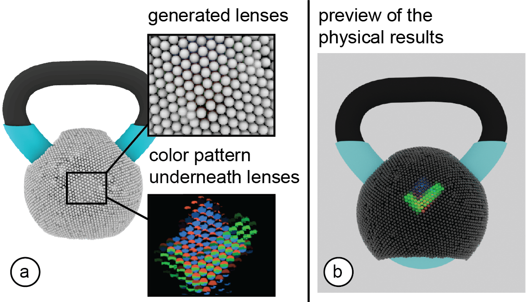
Figure 4: Previewing the resulting object: (a) Generating the lens geometry and underlying color pattern. (b) Simulating the optical result using ray tracing to provide an accurate preview of the object before fabrication.
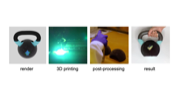
Clicking the ’export fabrication files’ button generates the fabrication files for 3D printing, i.e. exports the object geometry and the lenses (.vrml) and an image file for the color pattern (.png).Designer can then upload the fabrication files to the slicer and after slicing finished, send them to the 3D printer. In the next section, we describe the slicing and fabrication process as well as the post-processing techniques we used to fabricate the objects with lenticular surfaces shown in this paper.
FABRICATION AND POSTPROCESSING
We first explain which 3D printer and printing materials we use,and then detail our fabrication process, which includes slicing the3D model, 3D printing the object, and then post-processing the surface of the object. We then report on experiments investigating the print quality of different lens sizes as well as the color pattern resolution of our 3D printer.
Fabrication Process
3D Printer and Printing Materials: We fabricate our objects using a multi-material 3D printer that can print the object geometry,color patterns, and lenses in one pass. We fabricated all the objects in this paper using the Stratasys J55 3D printer, which uses polyjet technology. To print the lenses, we use the Stratasys polyjet material VeroUltraClear, a type of clear 3D printable acrylic. To print the color patterns, we use materials from the VeroVivid family (VeroCyan-V, VeroMagenta-V, and VeroYellow-V) in combination with VeroPureWhite as the base material, which can create different colors on a per-voxel basis.
Slicing: Before printing, we slice the fabrication file that contains the object geometry and lenses (.vrml), which was exported from the 3D editor. To do this, we load the fabrication file into the slicerGrabCAD that can be used with the Stratasys 3D printers. After loading the .vrml file, we associate each part with the corresponding print materials in the ’print settings’. To further improve the quality of the printed lenses, we use the ’glossy’ finish instead of the ’matte’ finish in the ’print settings’. Clicking the ’save’ button generates a file in .print file format, which we subsequently load into the 3Dprinter for fabrication.
3D Printing and Removing Support Material: After 3D printing, lenses printed at an angle are either fully or partially covered in support material. To remove the support material that the Stratasys 3D printers use (SUP710), we used an Objet Powerblast WaterJetmachine, which washes off the support in less than 15 minutes.
Polishing the Lenses: Although we chose the ’glossy’ 3D printing setting for the lenses, the lenses that are in contact with support material will still be matte since the 3D printer cannot use the glossy finish in those areas. To address this, we post-process the lenses by spraying 3 layers of varnish on the surface of the lenses.
Since the 3D printing process leads to imperfections in the lenses as well as in the color patterns, we ran a set of experiments to determine the print quality of different lens sizes and color pattern resolutions, which we report on in the next section.
Fabrication Quality of Different Lens Sizes
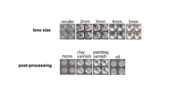
Our preliminary experiments showed that the quality of the fabricated lenses depends on several different parameters, such as the lens size, the orientation in which the lens is printed, and the post-processing technique applied to the lens after fabrication. We therefore fabricated lenses using different parameters and com-pared the physical result with the rendered view of the lenses to evaluate their quality.
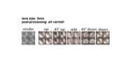
Procedure: We generated four different lens sizes, ranging from a diameter of 2mm - 5mm in 1mm increment, using the lens geometry as determined in Section 6. Since the print orientation also impacts the optical quality, we 3D printed each lens size in five orientations: (1) facing upwards, (2) facing 45◦upwards, (3) facing sideways,(4) facing 45◦downwards, (5) facing downwards.
After printing the lenses, we aligned the backplane of each lens onto an ink-jet printed checkerboard with a checker size of 500 microns (printer: Xerox Workcentre 7970, paper: HP Premium PlusPhoto Paper | Soft Gloss). We took pictures from the top of the lenses with a camera (model: Canon T3i, focal length: 18mm, dis-tance from lens top: 40cm). We then compared the photos with the rendered image of the same lens with the same checkerboard pattern, which shows the resulting image without any print imperfections (rendering engine: LuxCoreRender [31]).
To evaluate different post-processing methods, we compared four techniques: (1) no post-processing, (2) lenses coated with three layers of painting varnish spray (Liquitex), (3) lenses coated with three layers of clay gloss varnish spray (Krylon) and (4) lenses rubbed with baby oil ( Johnson). For each technique, we fabricated anew copy of the lenses. To make sure that the post-processing effect is stable, we put the post-processed lenses in a room for 14 days before taking photos.
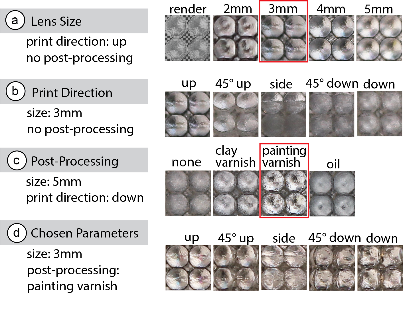
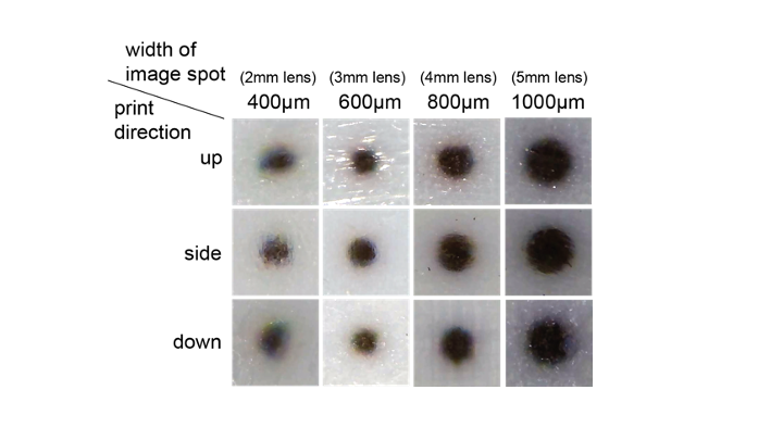
Figure 5: Fabricated lenses compared with rendered lenses.(a) Larger lenses have better fabrication accuracy, (b) lens quality varies among different printing directions, (c) clay varnish and painting varnish both improve the lens quality,(d) lens quality of our chosen parameters (3mm lenses with painting varnish)
Result: Figure 5 shows the photos of the lenses compared with the rendered image from the same viewpoint. For the lens sizes, larger lenses show an image that more closely resembles the rendered image than smaller lenses. Concerning the print orientation, lenses printed facing upwards result in the best lens surface quality be-cause no support material is needed and thus all parts of the lens are printed with glossy finish. All other angles need support material in varying amounts and thus the lens quality decreases. From those lenses printed with support material the best print quality was45◦upwards, followed by lenses facing downwards and 45◦down-wards, and the worst print quality resulted from printing lenses sideways. For post-processing, both types of varnish improved the glossiness of the lens surface, with the painting varnish providing the best surface quality. In contrast, the baby oil made the lens glossy when rubbed, but the effect faded away after 14 days.
Which lens size to use is a trade-off between image quality and overall image resolution. While smaller lenses are of less print quality, they provide a higher resolution, which more closely represents the details of the input image. We found that for our application scenarios, 3mm lenses with post-processing preserved the important visual features of our input textures while providing sufficient visual quality. However, for one of our example applications (ear-pod case), we chose to use 2mm lenses to fit more lenses onto the otherwise small geometry.
Resolution of 3D Printable Color Pattern
We also investigated the 3D printing resolution of the color pattern,which forms the image spots underneath the lenses. If the printable color pattern resolution is too low, the image spots assigned to the different viewpoints merge together on the backplane of the lens causing the viewer to see the wrong image from the viewpoint. The color pattern resolution required depends on the size of the lens,i.e. larger lenses have larger image spots (see next section: Lens Geometry Design).
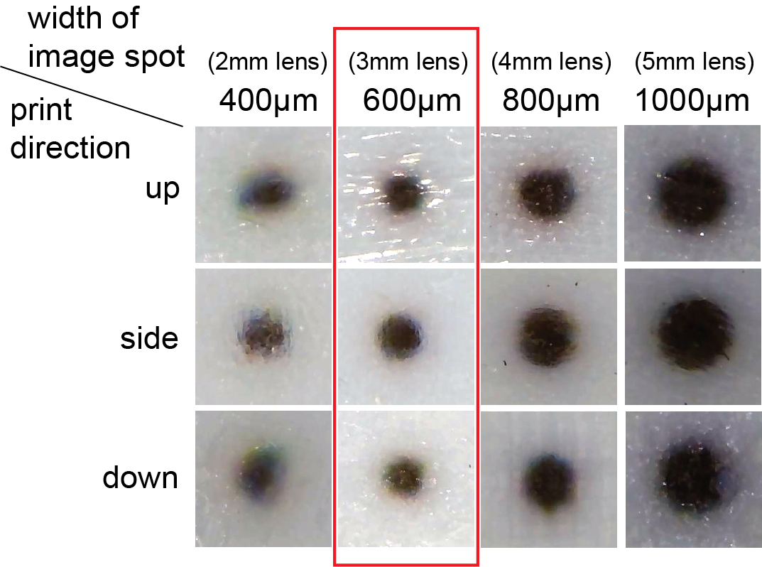
Figure 6: 3D printed dots of different sizes from different print directions. Dots that have a 600 micron diameter are the smallest that have good print quality.
Procedure: To determine whether the 3D printer’s resolution can accurately fabricate the image spots for different lens sizes, we ran an experiment in which we 3D printed circle patterns represent-ing the image spots of different lens sizes (2mm lens: 400 microns,3mm lens: 600 microns, 4mm lens: 800 microns, 5mm lens: 1000microns) and then analyzed their quality under a microscope. Toaccount for different print orientations, we printed the circle pat-terns on the top, side and bottom surfaces of a cube with a side length equal to 10 times the circle’s diameter. We then used a microscope (model: inskam-316) to take photos.
Result: As shown in Figure 6, the larger the printed circle pattern,i.e. image spot, the better the print quality. We found that the color pattern of 600microns, which corresponds to the 3mm lenses, was the smallest that had a good print quality with sharp edges. Thus,with our color print resolution, lenses that are 3mm or larger can maintain the computed number of viewpoints with different images.
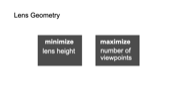
LENS GEOMETRY DESIGN
We next describe how we computed the lens geometry that represents the best trade-off between a large number of viewpoints and avoiding protrusion of the lenses from the object geometry). We then render an example lens with the resulting lens geometry to show that it supports the calculated number of viewpoints.
Optimal Lens Geometry: Figure 7a shows the three parameters that determine the geometry of a lens: (1) the diameter 𝑑𝑏𝑎𝑠𝑒 of the lens,(2) the radius 𝑟 of the top spherical surface of the lens that shapes its curvature, and (3) the height ℎ𝑏𝑎𝑠𝑒 of the substrate (the cylindrical base) of the lens. The overall lens geometry is determined by these three parameters, i.e. the ratio of𝑑𝑏𝑎𝑠𝑒:𝑟:ℎ𝑏𝑎𝑠𝑒. We further define the width of the image spot underneath the lens as𝐿as shown in Figure 7b.
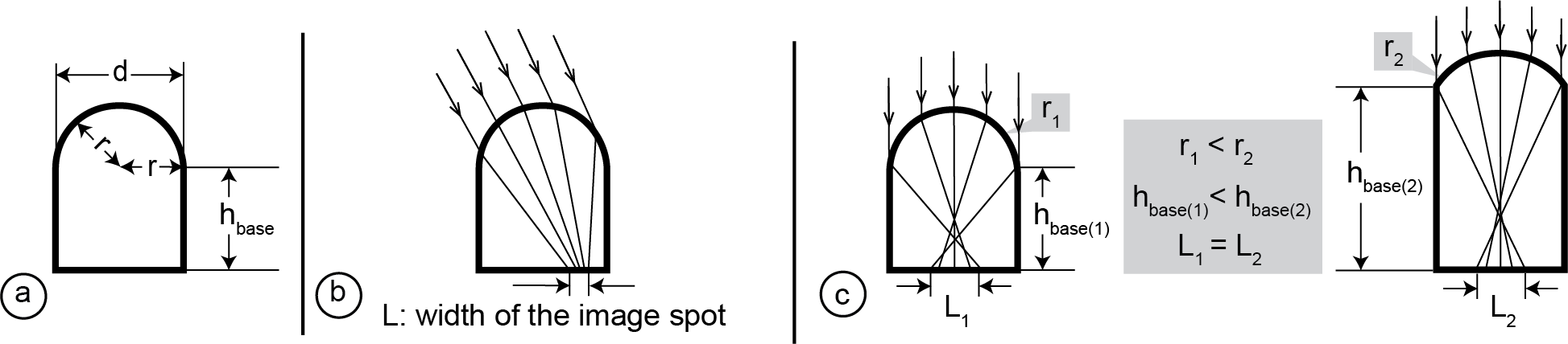
Figure 7: (a) Basic lens parameters: lens diameter𝑑𝑏𝑎𝑠𝑒, radius 𝑟 and substrate heightℎ𝑏𝑎𝑠𝑒(b) image spot 𝐿: the area underneath the lens that can be seen from one specific viewing angle, (c) to achieve the same image spot size, a smaller radius (i.e., more curvy lens), requires a smaller height.
The lens geometry determines how many viewpoints each lens can support. The number of viewpoints is determined by how many image spots fit underneath each lens. There are several factors that determine the size of the image spots. First, for a given lens curvature, the lens substrate has a specific height at which the image spot is minimized. The more curvy the lens surface is, the smaller the substrate height when it achieves its local minimum (Figure 7c).Since the lenses are added to the object’s surface, we want to minimize the height so that the lenses do not protrude too far out from the object geometry. We thus use the most curvy lens since it results in the smallest height and thus least protrusion from the surface. The most curvy lens is created by using the smallest radius r, which is 𝑑𝑏𝑎𝑠𝑒2.
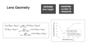
With the radius𝑟determined, we next find the lens substrate height ℎ𝑏𝑎𝑠𝑒 that minimizes the width of the image spot𝐿so that the lens can hold the largest possible number of image spots. For this,we use different lens substrate heights ℎ𝑏𝑎𝑠𝑒 as input and plot the resulting image spot widths. For a given lens substrate heightℎ𝑏𝑎𝑠𝑒,the image spot width𝐿also depends on the viewing angle, i.e. if the viewer looks straight down onto the lens, the magnification is larger and the image spot smaller than when the viewer looks at it from the side. We therefore plot the upper bound of the image spot width for each given lens substrate height. The detailed computation is included in the Appendix and the result is shown in Figure 8a.We can see that the image spot width𝐿is minimized when the substrate height ℎ𝑏𝑎𝑠𝑒=0.5𝑑𝑏𝑎𝑠𝑒 with the image spot width being𝐿=0.2𝑑𝑏𝑎𝑠𝑒.
In conclusion, the lens geometry that supports the highest number of viewpoints while protruding least from the object surface has a lens curvature of𝑟=0.5𝑑𝑏𝑎𝑠𝑒and a substrate height of ℎ𝑏𝑎𝑠𝑒=0.5𝑑𝑏𝑎𝑠𝑒. Therefore, the lens geometry we use has a ratioof𝑑𝑏𝑎𝑠𝑒:𝑟:ℎ𝑏𝑎𝑠𝑒=2 : 1 : 1(Figure 8b).
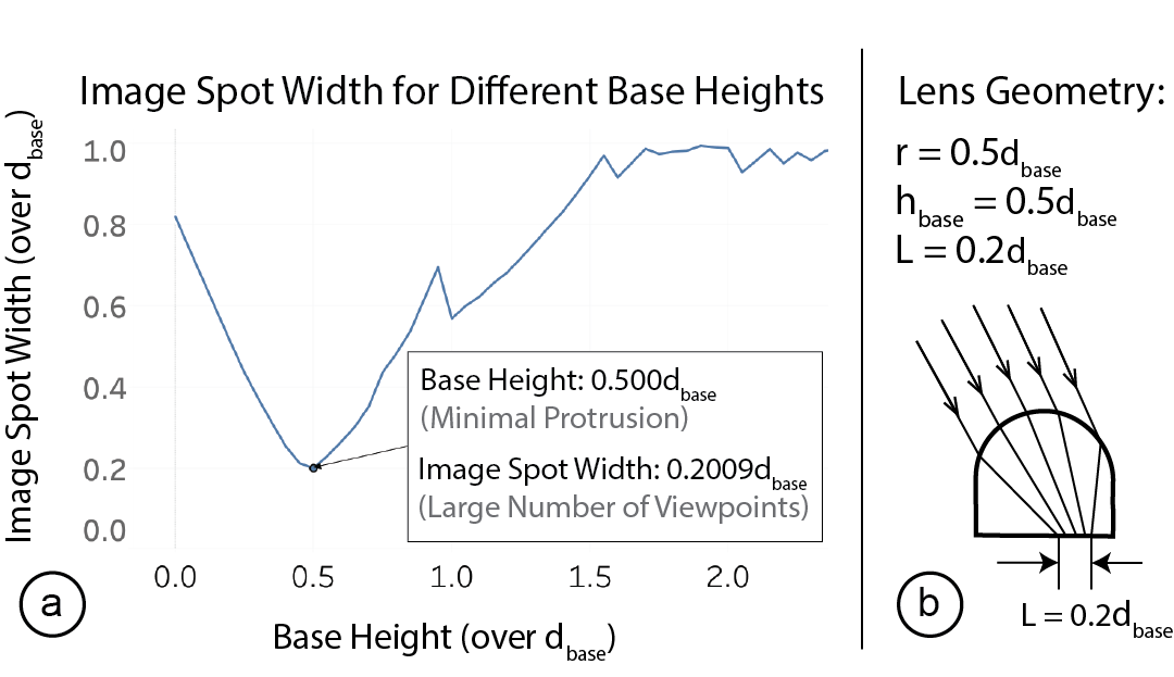
Figure 8: (a) Finding the base height that minimizes the image spot for𝑟=0.5𝑑𝑏𝑎𝑠𝑒; (b) the resulting lens geometry is𝑑𝑏𝑎𝑠𝑒:𝑟:ℎ𝑏𝑎𝑠𝑒=2 : 1 : 1, which results in 𝐿=0.2𝑑𝑏𝑎𝑠𝑒.
Viewing Range: The lens geometry results in a viewing angle range of 83.6◦, i.e. the viewer can see the correct image spot when they are no more than 46.8◦=83.6◦/2 away from the upwards direction of the lens. We determined this value by tracing 20 parallel viewing rays from each viewing angle and determined the viewing angle valid when all viewing rays from a viewing angle were reflected onto the backplane where the image spot is supposed to be located(see Appendix of the paper).
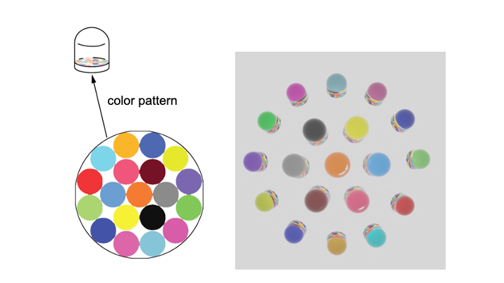
Number of Viewpoints: As mentioned above, the width of an image spot from any viewing angle is at most𝐿=0.2𝑑𝑏𝑎𝑠𝑒. To determine the resulting number of viewpoints, we calculated the maximum number of image spots that can fit into the lens backplane. Although the exact image spots can have non-circular shapes,𝐿represents the upper bound of the image spot width across all viewing angles. We used the Wolfram Alpha calculator’s circle packing function [52]and found that 19 image spots fit into the lens backplane. To verify that we can support 19 different viewpoints, we created a lens with 19 different image spots (Figure 9a) and simulated the appearances this lens creates from each of the 19 viewpoints using ray tracing. Figure 9b shows the result, i.e. that the lens is indeed capable of creating different appearances from 19 different viewpoints.
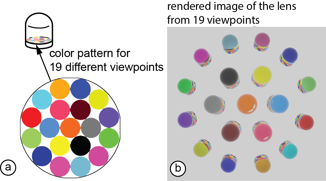
Figure 9: (a) Our lens geometry allows packing 19 image spots onto the backplane of a lens and thus can support 19 viewpoints with different images; (b) ray traced results of the lens showing 19 different colors from different viewpoints.
To evaluate how many different viewpoints can be achieved considering the limitations of current fabrication technology, we fabricated lenses at different angles (facing up,45◦up, sideways,45◦down, down). We printed 19 lenses per angle with each lens containing a different number of viewpoints, ranging from 1−19 viewpoints. After fabrication, we took pictures from all visible viewpoints. Our results show that lenses printed facing upwards and downwards have the highest number of visible viewpoints,i.e. the upward printed lens can show up to 19 viewpoints and the downward printed lens can show up to 14 viewpoints. Other print orientations had smaller number of view points (i.e. 45◦up: 12 viewpoints,45◦down: 9 viewpoints, sideways: 7 viewpoints).
IMPLEMENTATION
Our 3D editor is implemented in the 3D modeling softwareRhino3Das aGrasshopperplugin. Our software pipeline first distributes the lenses across the surface of the 3D model. It then maps the pixels of the different input 3D color textures to the lens positions on the3D model. Next, it computes for each lens how the color pixels of the different 3D textures should be arranged on the backplane of the lens to show the correct appearance for each viewpoint. Finally,it generates the fabrication files and exports them.
Distributing Lenses Across the 3D Model
Our goal when distributing the lenses across the 3D object surface is to pack them as closely together as possible while not colliding with each other. Two lenses are not colliding when the distance between the two lens centers is equal or greater than the diameter of the lenses. Since lenses are uniform circles, an efficient way to pack them is hexagonal packing [54]. Hexagonal packing can be achieved by first dividing the surface into equilateral triangles and then placing a lens at each corner of the triangle. Since lenses should not collide, we set the edge length of the equilateral triangle to the lens diameter.
To implement this, our system first converts the 3D model into a triangular mesh using the instant meshes open source library [21](Figure 10a/b). Since instant meshes requires an .obj file as input,our system temporarily exports the 3D model from our editor and uses the exported file for the instant meshes conversion. In addition to the 3D model geometry in .obj format, instant meshes requires several parameters: first, instant meshes requires the target face count, i.e. the number of faces into which the mesh should be converted. Our system determines the number of faces by dividing the surface area of the 3D model by the area of the corresponding equilateral triangle. Next, instant meshes requires as input the rotational and position symmetry. Setting them to a value of ’6’ results in a hexagonal-directional field suitable for triangular packing. Once instant meshes finished the conversion, our system imports the converted triangular mesh back into our design tool. Our system then uses the corners of the triangles, which represent all the vertices of the mesh, as the centers for the lenses to place the lenses across the 3D surface (Figure 10c/d).
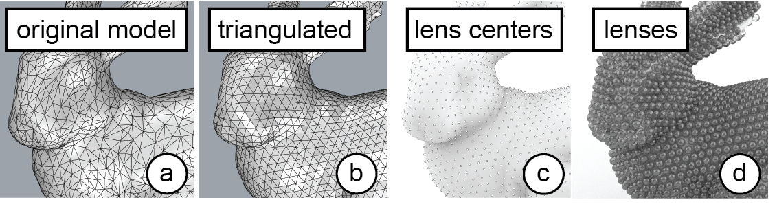
Figure 10: Placing the lenses: (a) original 3D model, (b) triangular mesh with equilateral triangles, (c) each triangle corner (vertex) is a location for a lens center, (d) lenses placed.
Mapping Color Pixels to Lens Locations
Once our system positioned the lenses across the 3D model’s sur-face, it next maps the color pixels of each texture image to the lens positions on the 3D model (Figure 11a). To know which texture pixels belongs to which lens, our system uses UV mapping, which maps a vertex on a mesh to a 2D coordinate on the texture image.When a 3D object with texture mapping is imported, a list of vertex-to-UV coordinate mappings is already included in the 3D model.For points on the surface of the 3D model that are not vertices, our system can further compute their UV-coordinates in the texture image using their barycentric coordinates, i.e. by finding which face they are on and then interpolating them as the weighted average of the vertices on the face.
After computing all UV coordinates, our system maps each color pixel in the 3D texture to a lens. To do this, our system first finds the lens center’s pixel location in the color texture using the UV map-ping. Assuming that the input geometry has an even UV-mapping, i.e. the distance between two points on the texture is proportional to the geodesic distance between the source points on the object,our system then finds the pixel-radius of each lens on the texture by sampling a point on the circumference of the lens and then finding the distance between its corresponding pixel and the lens center’s corresponding pixel. Therefore, every pixel that is within the pixel-radius distance to the lens center’s corresponding pixel are mapped to the lens.
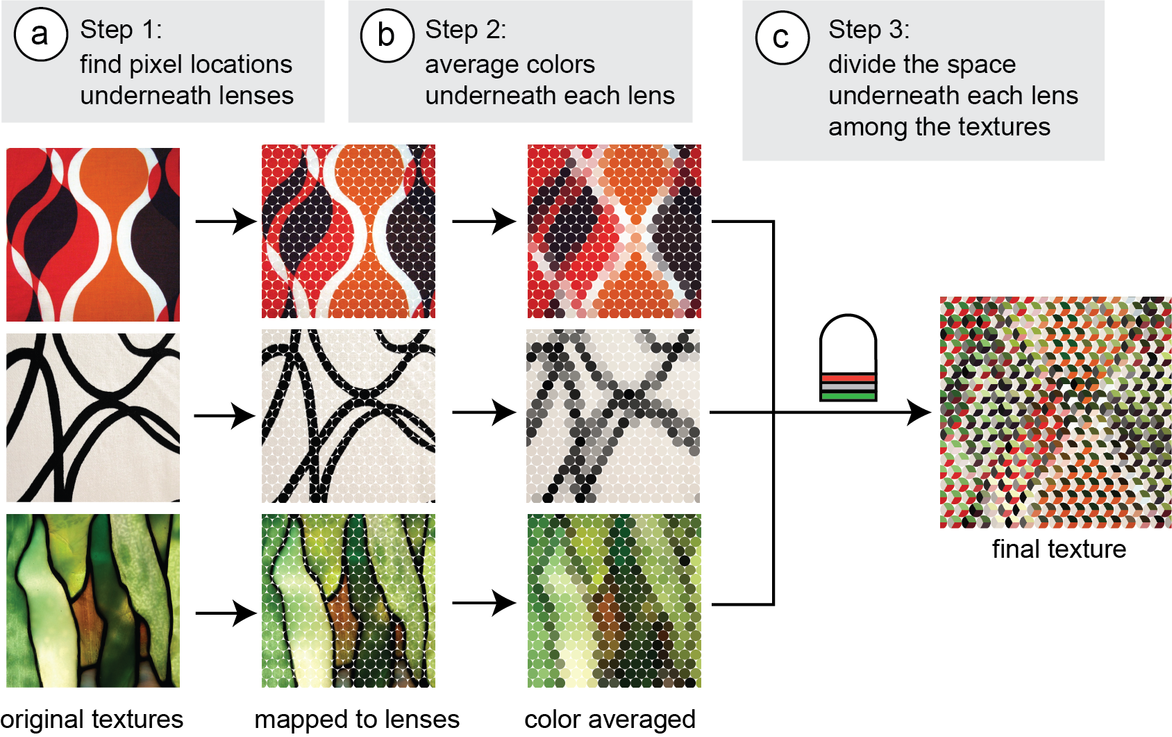
Figure 11: Mapping color pixels onto lenses for each 3D texture: (a) Find which pixels are underneath which lens for each texture. (b) For each texture, average the color under-neath each lens. (c) Divide the space underneath each lens using ray-tracing and assign the averaged color of the corresponding texture for each lens.
Our system requires that all 3D textures have the same UV mapping. Thus, once the UV mapping is computed, we can reuse the assignment of color pixels on a 3D texture to a specific lens position on the object geometry for all viewpoints and their 3D color textures.
Averaging Color Pixels in each Image Spot
Next, our system averages the colors of all pixels in an image spot that belong to the same viewpoint (Figure 11b). We do not keep the individual color pixels in an image spot because when the viewer shifts the head slightly, they would see a different color pixel each time, resulting in unrelated patterns even with slight head movement. In addition, the image spot is very small due to the magnifying effect of the lens. Thus, printing all color pixels from the input texture into the small image spot would require a print resolution beyond what our 3D printer is capable of. The smallest pixel size that our 3D printer supports is 200 microns,which translates to only 7 pixels for the image area underneath a 3mm lens. Because of this, our system averages the color of all pixels in an image spot that belong to the same viewpoint.
Arranging Image Spots Underneath a LensAccording to the Viewpoint
The previous processing step determined the average color assigned to each lens for each of the input textures. Next, our system arranges the average colors from the different input textures underneath each lens to show the correct color at each viewpoint (Figure 11c).
Before our system can distribute the image spots underneath the lens, it first has to determine which area underneath the lens is visible from which viewpoint. To accomplish this, our system casts rays from different viewpoints to the top surface of the lens. When the various rays hit different points on the top surface of the lens, they enter the lens at different angles and thus reflect off different positions at the bottom of the lens (our system approximates the back of the lens with a flat plane because of the small lens size).Since the color pattern is placed at the bottom of the lens, we know that the positions were the rays reflect off the backplane are visible from the specific viewpoint from which the ray was cast. We thus only keep the color of the texture that should be visible from this viewpoint and delete all other textures in this area.
Exporting the Fabrication Files
Finally, once the lenses are generated and the color pattern is correctly distributed across all lenses, our system exports the fabrication files, i.e. the geometry file (.vrml) with the lenses and the object geometry, and the color pattern image (.png) that is referenced in the .vrml file. To prepare for rendering, our system also generates a viewpoint file (.txt) that records the 3D coordinates of the viewpoints defined in the system, which the render environment usesas the locations for the render cameras. Our system renders the exported object using the ray tracing plugin LuxCoreRenderer in Blender.
APPLICATION SCENARIOS
Being able to design objects that look different from different viewpoints enables a wide range of novel applications in product design and HCI. In the following section, we highlight several application scenarios that focus on using 3D lenticular objects. In the scenarios,the objects demonstrate that our system can produce objects with:(1) different geometric complexities (e.g. single and doubly curved surfaces), (2) image complexities (e.g. patterns, symbols and text),and (3) number of distinct images (ranging from 2 to 5).
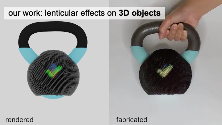
Guiding User’s Body Poses
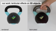
Our work enables the development of tangible objects that can guide users into placing or holding the object at a specific body pose. Figure 12 illustrates this at the example of a piece of exercise equipment, i.e. a kettlebell. This lenticular kettlebell guides the userinto the correct exercise position, i.e. a front raise, by displaying if it is held at the correct height. The kettlebell displays a downwardsa rrow if it is held too high (Figure 12a), an upwards arrow if it is held too low (Figure 12c), and a check mark when the user holds it at the correct height (Figure 12b). This can prevent the user from exercising at the incorrect body pose, which has been shown to leadto injuries [12]. The kettlebell is an example of a lenticular object that displays symbols (up/down arrow, checkmark) printed with 3mm lenses on a doubly curved surface with three different viewing angles (low angle, eye level, high angle). In this example, rather than printing the entire kettlebell, we bought a 10lb kettlebell and augmented it with a 3D printed lenticular shell.
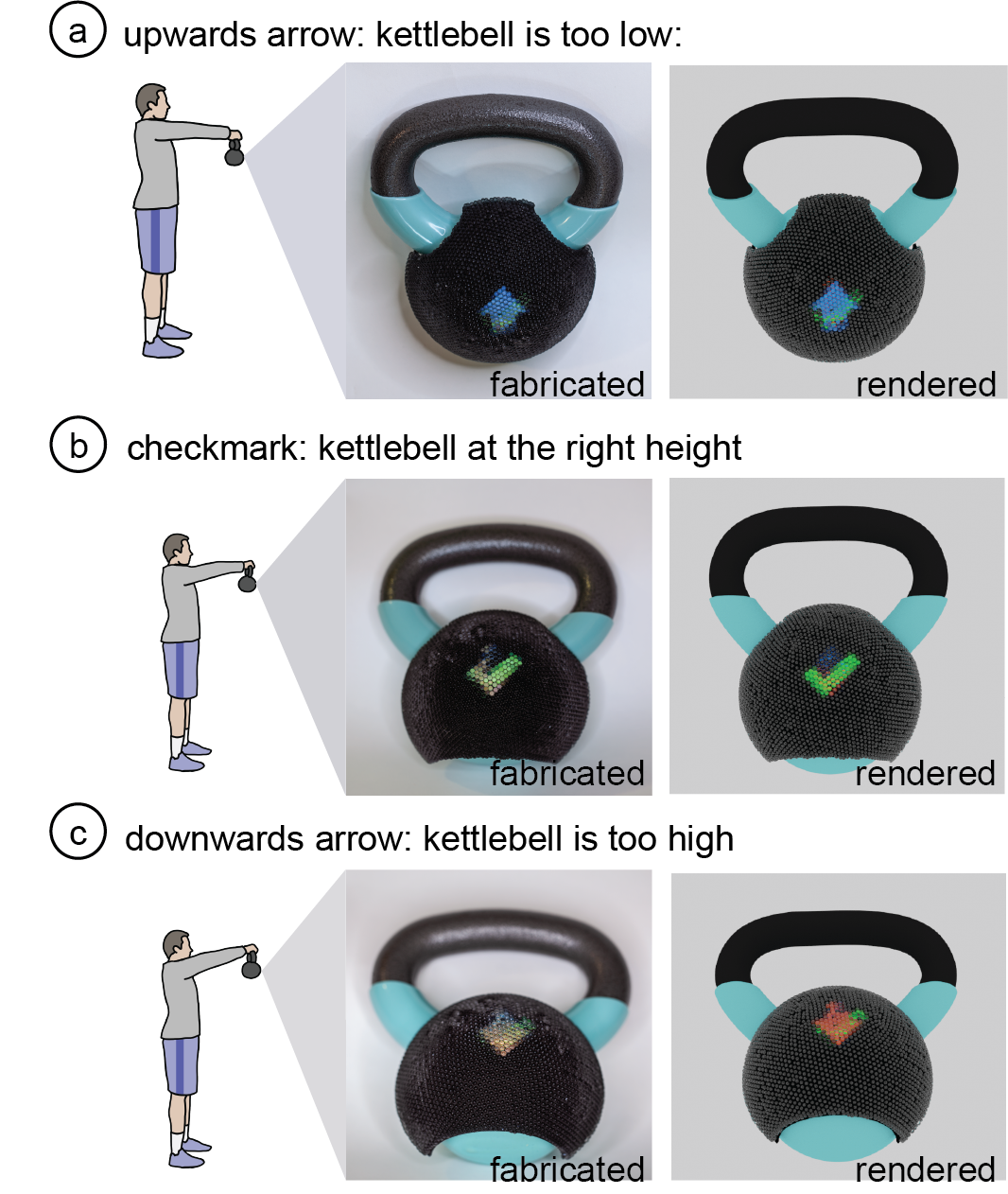
Figure 12: Pose Guidance: this kettlebell guides the user to a correct front raise pose by displaying arrows when the kettlebell is too high or too low and a check mark when the kettlebell is at the right height.
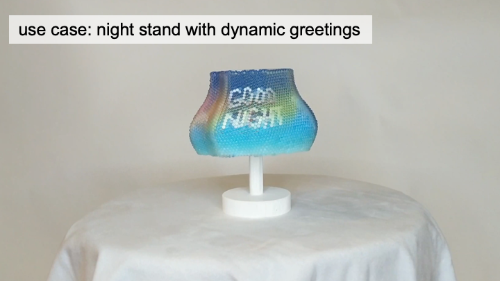
Dynamic Message According to User’sPosition
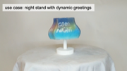
Our work also enables objects that display dynamic message or surface pattern according to the user’s position. Figure 13 shows this at the example of a lampshade made for a user’s bedroom that displays "Good Night" when the users lays in bed (i.e. looks at the lamp from the same height), and displays "Good Day" when the user looks at it while sitting up in bed (i.e. looks at the lamp from above). This application is an example of how lenticular objects created with our system can display text messages (’Good Night’,’Good Day’). The lamp was printed with 3mm lenses on a doubly curved surface with two different viewing angles (same height as the lamp, above the lamp).
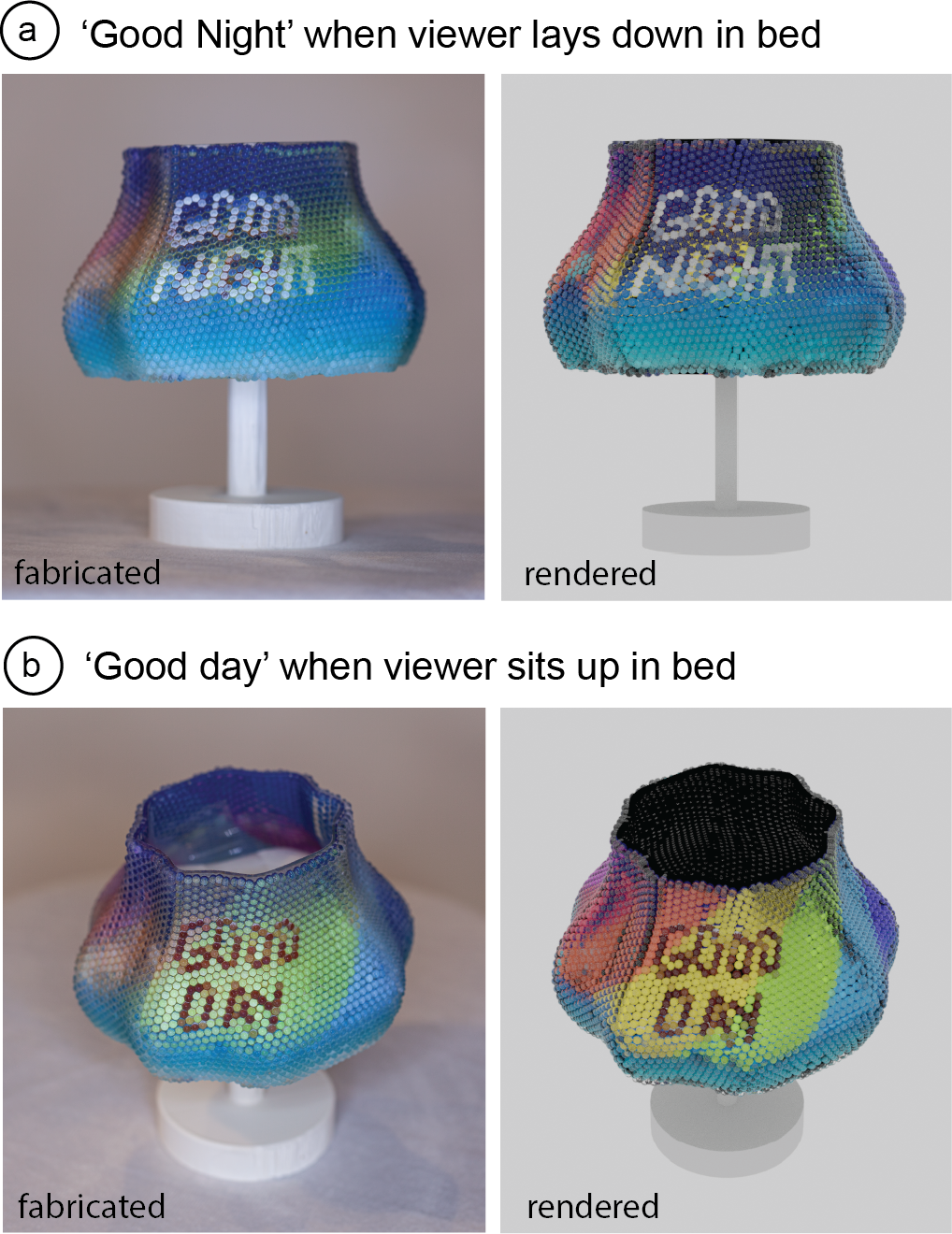
Figure 13: This lampshade displays different greeting mes-sages when the users looks at it from different heights (laying down in bed vs. sitting up in bed).
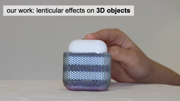
Dynamic Visual Effects for Product Design
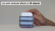
When a user plays with, passes by or moves around an object, they change their viewpoint towards the object. We leverage this to create dynamic visual effects on products as part of the object’s product design. Figure 14 shows this at the example of an earpod case that transitions between different colors when it changes its viewing angle with respect to the viewer. This application is an example that displays a pattern (colorful stripes) printed with 2mm lenses on a surface that is flat on the front and doubly curved in the corners with five different viewpoints (one for the yellow, green,cyan, purple, magenta stripe patterns). The discrepancy between the fabricated and rendered earpod case in the right-most viewpoint results from fabrication limitations, i.e. since the earpod case was printed with 2mm lenses the printing resolution for the color pattern is not high enough to support the magenta sections.
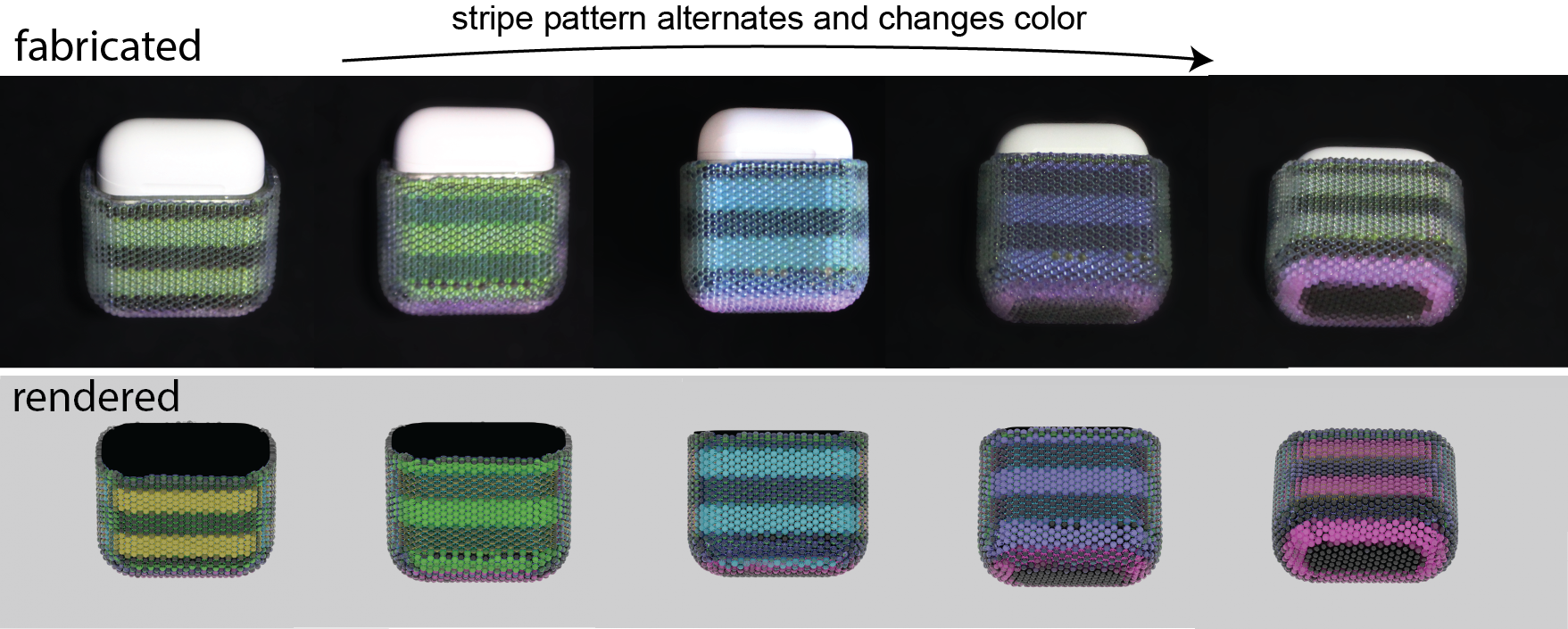
Figure 14: This earpod case flickers between five alternating bright-dark stripe patterns of different colors as the user handles it, creating unique aesthetics effects as part of the object’s product design.
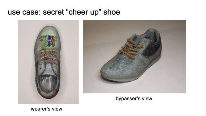
Images Only Seen by Specific Users
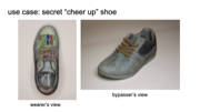
Different viewers tend to have different viewing angles on the same object. We can use this to create appearances that are only accessible by specific users. Figure 15 shows this at the example of a visual design that is only visible from the user’s viewing angle.When the user looks down on their pair of shoes, the pair of shoes display a ’Cheer Up’ message, however, other people cannot seethe message and instead see a plain shoe design. This application is an example of how our system enables displaying a text message.The pair of shoes was printed with 3mm lenses on a doubly curved surface with two different viewpoints (regular shoe design [47]from the side and ’cheer up’ message from the top). The entire shoe including the lenticular lenses was printed in one piece.
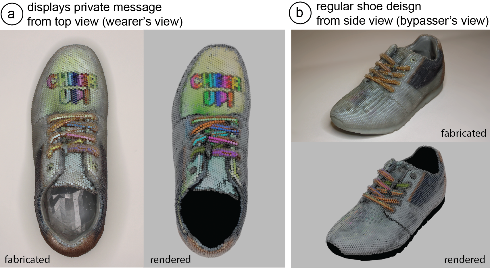
Figure 15: Visual designs only visible from the user’s viewing angle: (a) A pair of shoes that shows a supportive message to the wearer looking down on the shoes, which(b) other people looking from the side at the shoes cannot see.
In summary, our four application scenarios demonstrate that our system can create lenticular objects with different geometric and image complexities as well as different number of viewpoints. In the next section, we will discuss limitations and future work of our system.
DISCUSSION AND LIMITATIONS
Our current implementation is subject to several limitations, which can be addressed in future work:
Impact of Lenses on Object Geometry and Surface Haptics: In our current work, we place the lenses on top of the surface of the3D model, which extends the geometry by a lens layer of 3mm.While a layer of such lenses may not be an issue for larger objects,smaller objects with thin geometries will substantially increase in thickness. For future work, we plan to integrate the lens substrate into the object geometry to minimize protrusion from the surface. In addition, covering objects with lenses changes the tactile qualities of the object. We hope that with future developments in 3D printing, it will become possible to print lenses that are small enough that they no longer change the surface haptics. This may also address another challenge, which is that lenses that protrude from the surface can collide when geometries are highly curved, which can happen in our system but would no longer occur when lenses are smaller.
Impact of Non-Uniform UV and UV Seams on Color Pattern: As we explained in the implementation, we assume that the input geometry has a uniform UV texture mapping. If the UV texture mapping is uniform, the circular lens geometry refers to a circular area on the input texture, thus the mapping in our system creates the correct result. If the UV mapping is non-uniform, the circular backplanes of the lenses are mapped to non-circular areas on the input texture and thus assuming a circular-mapping may result in lenses being assigned to the wrong color pixels. This can be resolved by sampling a large number of points on the circumference of the lens and mapping them to the input texture to accurately represent the non-uniform mapping. Another problem that can occur when performing the UV mapping is that the lens center and the sampled point on the lens circumference may be on opposite sides of theUV texture when the lens is located on a seam. This causes the mapped radius to be much larger than the actual radius. We detect such cases by setting an upper bound for the mapped radius and subsequently do not assign a color. For future work, we plan to perform UV mapping for all points inside the lens’s backplane and not just the circumference so that all of the points are mapped to the correct location on the input texture.
Showing Optical Limitations in User Interface: Our current user inter-face supports the designer in specifying viewing angles, assigning color textures, and generating fabrication files for the lenticular object. However, our current system relies on the designer to check in the rendering environment whether the generated result matches their specified design. In cases where the defined viewpoints exceed optical limitations, e.g. a viewpoint is outside the viewing range of a lens or two viewpoints are too close together, there can be crosstalk between different images. In future iterations, we will extend our user interface to only support those viewing angles that are valid.
Fabricating Lenticular Objects on Consumer Level 3D Printers: While we fabricated our lenticular objects on a high-end Stratasys J55 3D printer, it may also be possible to fabricate lenticular objects on low-cost 3D printers, albeit at the expense of manual assembly. For instance, Formlabs 3D printers have been shown to be capable of 3D printing lenses, while the Da Vinci 3D Printer) can print the color patterns in full color. Thus, by printing the lenses as a separate shell, it may be possible to fabricate lenticular objects on consumer level 3D printers.
Dynamic Lens Sizes and Other Types of Lenses: In our current system, all lenses on the object’s surface have the same size. While this is sufficient for scenarios that requires an even distribution of viewpoints, some scenarios might benefit from having lenses of different sizes located on different parts of the object’s surface. For future work, we plan to improve our algorithm to support dynamic lens sizes based on the required image resolution and number of viewpoints. In addition, while in this paper, we have focused on spherical lenses, other lens types, such as cylindrical lenses, exist. A benefit of cylindrical lenses is that they have higher spatial resolution while having the drawback that different viewpoints can only change along one direction. Figure 16 shows an application of this that we created manually: a minimalist product that only shows text instructions when it is held at eyesight and is otherwise clear.Compared to the text in the shoe application, the text resolution in this minimalist design example is higher. Since the application only needs to support one direction of movement, cylindrical lenses are sufficient to support this transition.
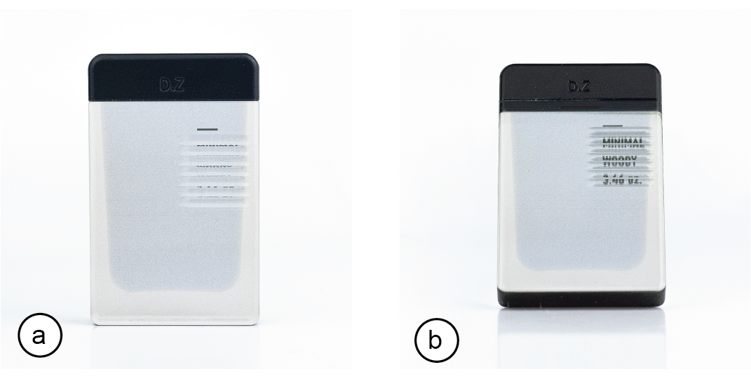
Figure 16: Cylindrical Lenses: A container that shows information only when needed: (a) the container does not show any text when looking from an upper angle, (b) the container shows informative texts when held at eye level.
CONLUSION
In this paper, we presented a method to extend lenticular displays to 3D object geometries, enabling 3D objects to look different from different viewing angles. We showed how our design tool supports designers in creating 3D lenticular lens displays by enabling them to define viewpoints and assign corresponding color textures. We also provided information on the fabrication process and evaluated the 3D printing quality of different lens sizes, the print resolution of the color pattern, as well as the effects of different post-processing techniques. We discussed our implementation pipeline that automatically computes the lens distribution across the object geometry and assigns the correct color pixels to each lens to achieve the desired appearance from each viewing angle. We then demonstrated various example applications that highlight different geometric and image complexities as well as different numbers of viewpoints.For future work, we plan to further improve our implementation by integrating the lens substrate into the geometry of the object,improving the UV-mapping algorithm to cover non-uniform UVmappings and seams of the UV textures, and to extend our 3D editor to consider optimal limitations. In addition, we plan to explore the use of dynamic lens sizes and other types of lenses, such ascylindrical lenses.
ACKNOWLEDGEMENTS
We thank Neil Gershenfeld for granting us access to the StratasysJ55 printer in his lab and Tom Lutz for 3D printing our models onthe 3D printer. This paper is based upon work supported by theNational Science Foundation under Grant No. 1716413.